- Verifies that the style is configured with invisible components
- Checks if the layers (of the device and its components) are on/unfrozen
- Note that the device icon in the Prospector is marked with
 , if so, it may be that
the section measurements cause solid modeling errors, but it may also be that the Constructor has errors.
In this case, the icon
constructor will also be checked
- Make sure the fixtures style is representing block or plan projection. These elements are drawn on the Z=0 plane and the device probably has a different Z. turn off these styles
- It could be that one of the devices doesn't have a reference surface, so it has Z=0, the others can have Z very different. Fix the reference surface
- Prefer SPREVIEW command over ObjectViewer
- Only linear/point or point/linear connections are allowed
- Only a linear/longitudinal device can be connected to the output of a point device
- Linear/longitudinal devices only allow one point device at the input and one at the output
- Sewage Networks are made only by structures and pipes, there are no superficial devices, which would be the longitudinal devices
- The device must be marked as "existing" and in this case, it is not possible to modify its geometry, only the style, rule or things that do not interfere with its geometry/position
- You may have pipes connected to the PV with elevation lower than the elevation you are trying to set on the PV, in this case, climb the pipes before climbing the bottom of the PV
- It may be that the resulting minimum PV height is less than the minimum allowed height, in which case change the model to accept the maximum and minimum heights you are trying to arbitrate
- Check in the table properties, if it is marked as automatic calculation
- Verify that the table style includes the correct type (linear/point device) or the Constructor of the modified device
- Check that the table selection type includes the device (if the selection is a polygon type, would the device be inside that polygon?)
- For them to appear, the network must be gravity (drainage or sewer)
- The Constructor of the linear device must have a section defined hydraulics:
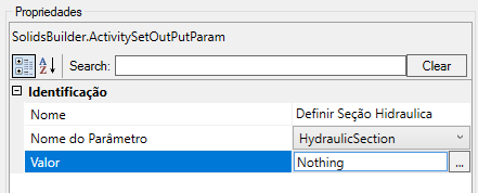
In the example above, the hydraulic section is not defined
It must exist in the model and can be:-
 Polyline, for the case of open sections (trapezoidal, triangular, etc)
 -
 Region, for the case of closed sections (circular, rectangular, etc)
A similar situation can occur with SWMM, as Conduits have cross section to be defined.
You can use the SWMM section in the hydraulic section:
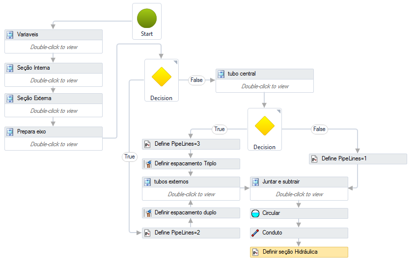
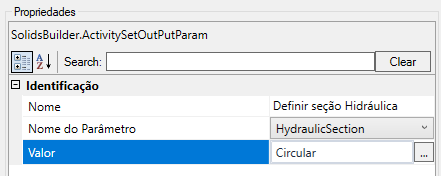
In the last activity, Define Hydraulic Section
defines the hydraulic section to be the section
 Circular:
-
Example:

In the image, there is any text in the Final Location / Final Connector Filter property, whereas in the connection box Constructor:
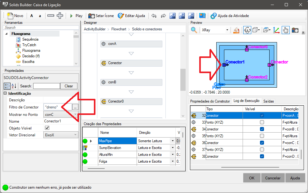
The connector specifies that only "drain" should be connected to it
Consider a capture box. It can plug into pipes, gutters or drains. Pipes are buried, while gutters are not. The drains can be of the "shallow" type, that is, they are below the superstructure of the floor, therefore, they do not connect in the same elevation of pipes or gutters. Therefore the connector needs to specify the expected connection type.

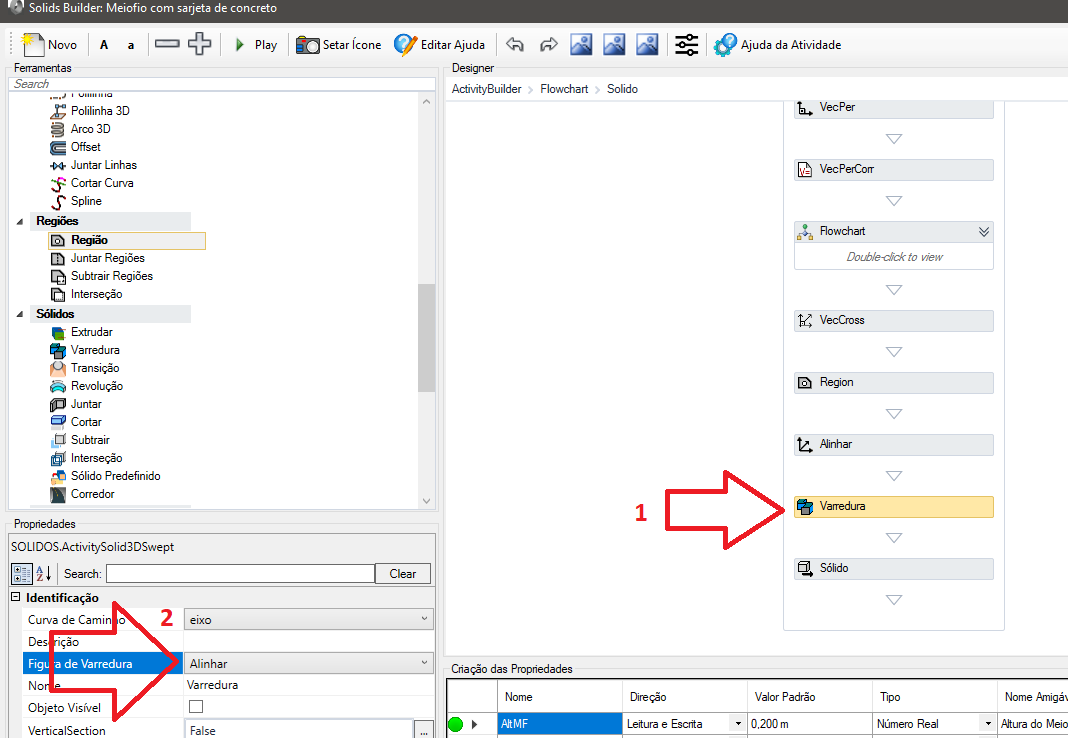
This error occurs because it is necessary to align the section to the axis before executing the activity. In some cases, AutoCAD crashes when using the "Region.CreateFromCurves()" method, because the section is in some UTM coordinate (x and y very large) and the section is very small (area less than 0.1 for example) and it shows the error "degenerate or unsupported object rejected".
To fix this, use the tool
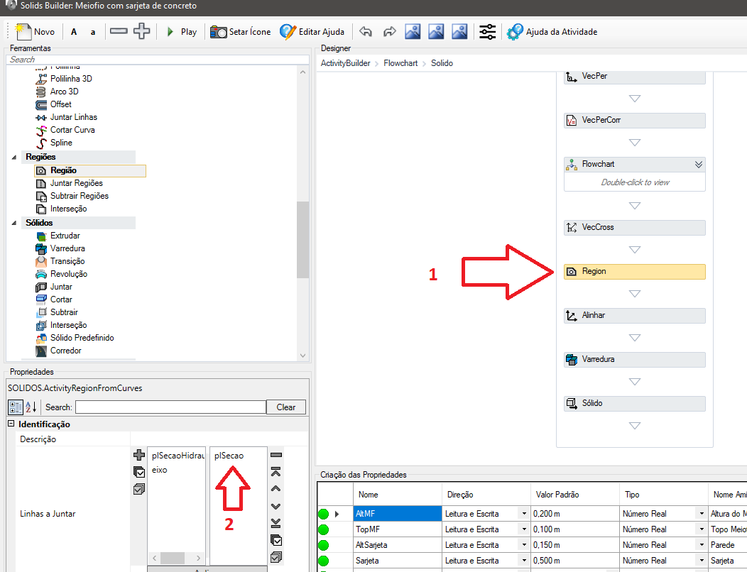
And then transform the region, using
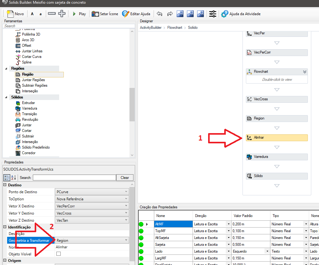
And then create the solid using the transformed region:
When you try to manually launch a device using the SNETWORK or SEDITNETWORK command, A fatal error occurs, closing Civil 3D, such as this:
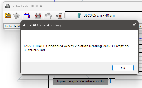
This error is related to video card settings. To fix, call the GRAPHICSCONFIG command and enable hardware acceleration