 SEDITNETWORK
SEDITNETWORK
SEDITNETWORK
The command
SEDITNETWORK creates devices in a device network.
To use, call SEDITNETWORK from the command line, menu, toolbar, context menu, Ribbon or the corresponding network node:
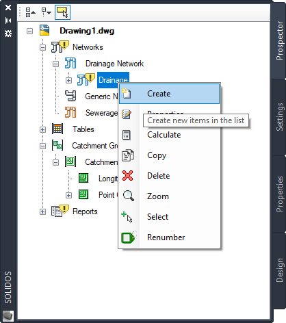
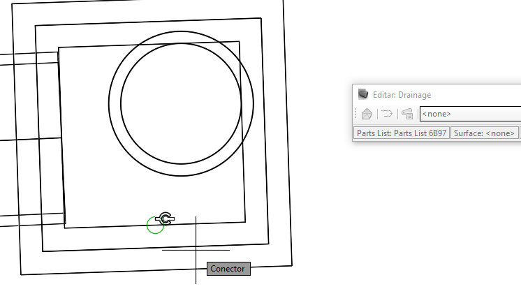
An edit bar will appear:

It has the following buttons:
 Surface - To change the reference surface of inserted devices after editing this property
 Excavation Surface - To change the excavation surface of inserted devices after editing this property
 Alignment - To change the reference alignment of inserted devices after editing this property
 Profile - To change the reference profile of devices inserted after editing this property
 Consumption Sector - Associates the created pipe with a Consumption Sector. Applies to sewer and water
 Materials List - Changes the Materials List associated with the network
 Draw Point - Draws only point device
 Point by Blocks - Converts selected blocks to point devices
 Point by Polyline - Inserts point devices at the vertices of polylines
 Draw Linear - Draw only linear or longitudinal device
 Linear by Polyline - Converts lines and polylines to linear or longitudinal devices
 Longitudinal by Alignment - Creates and associates a longitudinal device to an alignment/profile
 Draw Both - Draw connected point and linear devices
 Connect Linear/Linear - Enables/disables the connection between linear devices, creating a null point device between them
 Connect Point/Point - Enables/disables the connection between point devices, creating a null linear device between them
 Connect Point/Point - Splits an existing linear device
 Note: It is necessary to define the typical section of the point device in the typical point sections box
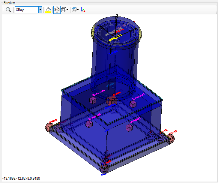
When drawing the devices, the program considers that you want to connect one device to another, so it will capture the connection points of the devices.
In the image below, magenta cubes mark the
 connection points of a device:
In plan view, they appear when there is an active insert device command:
These connection points will be used to reposition the devices linear or longitudinal dragging point devices.
If any device is disconnected when it should be, select it and drag the grippoint over the one where it should be connected. The connection icon will appear. Drop the selected device onto it.
Note: Not every device can be added to a given network. Each network has a set of device types that can be entered:
 Drainage Networks
 Sewage Networks
 Pressure Networks
Note:
 Device networks that are
 external reference, can only edit styles for labels and device projections.
If you need to rename, or otherwise edit, do so on the source file.
Note: To be able to Use this command, a
license is required. Otherwise, you will only be able to view the network.