SOLIDOS Modeler - Connector
 Connector - creates a point given X, Y and Z ordinates, which can be read by OSNAP NODE:
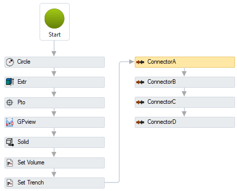
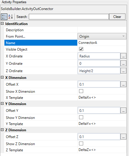
The Connector activity has the following properties:
-
Identification
-
Name - name of the activity
The point name must follow the naming rules
-
Show on Point - the connector must be associated with a point, choose it from the list
Observe the properties of the linear devices after connecting them to the point device, in:
- Input/Start Connector
- Output/End Connector
-
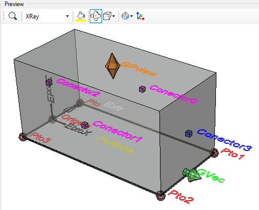
Object Visible - indicates whether or not the point should be drawn in the preview
-
Directional Vector - an vector that indicates the direction of the connector, or the vector normal to the plane where other devices will connect
For example, a pipe, when connecting to the manhole, does not necessarily do so orthogonally, in this case, it may be necessary to "cut" the end of the pipe so that it fits better in the structure.
In this case, use this property to calculate the cut angle
Observe the properties of the linear devices after connecting them to the point device, in:
- Input/ID of Initial Connector
- Output/ID of Final Connector
-
Connector Filter - text that will be used to filter the connector when choosing the closest one
Use simple words, which efficiently indicate what type of linear device the connector should serve, for example:
-
ditch - for ditches or gutters
-
Pipe - for Pipes
Consider that a collection box can connect with pipes, ditches, drains.
Pipes are buried and trenches are not.
The connector
appropriate should be selected.
- Connector Id - ID to be assigned to the connector
It will be used by linear devices to remember which connector they are connected to
Observe the properties of the linear devices after connecting them to the point device, in:
- Input/ID of Initial Connector
- Output/ID of Final Connector
If the text gets too big/small, or the sphere that represents the point gets too big or small, use the buttons ( A, a,
 ,
,
 ) at the top of the screen to change the preview
When you are When launching the network, by bringing the insertion point of the structure close to the initial or final point of the tube, the program shows that it can connect:
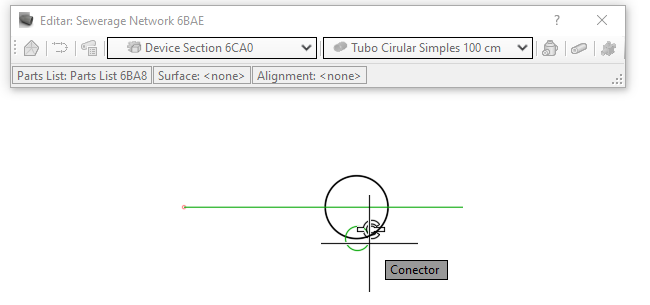
Note that the icon appears, indicating that the devices will be connected if the point is clicked
All the connectors of the device also appear, which can be in the color:
- red: The device cannot connect to this connector because it violates one of the connection rules
- green: The device can connect to this device, to this connector
If you bring the linear device close and capture the connector osnap, it will be stretched to the connector
 Note: For the connector osnap to appear, check the context menu of "Object Snap"