How to Use the Constructor Designer
The SOLIDOS Constructor is a visual programming type, or Low Code, if you prefer. It consists of a sequence of activities that perform
roles and that relate to achieving a more complex goal.
Think about the sequence of actions you would take to create a parallelepiped using AutoCAD's native tools:
- Having some information such as:
- Establish a reference point, or point of insertion of the parallelepiped, normally the Origin
- Click the
 points in AutoCAD's Model Space, where the coordinates of these points are linked to the above properties
For example, to draw a rectangle, click 4 points:
- P1, starting from the origin, add the coordinates X=-Length/2 and Y=Width/2
- P2, in relation to P1, add to X, Length
- P3, in relation to P2, add to Y, -Width
- P4, in relation to P3, add to X, -Length
Note that I used relative coordinates. You could use absolute coordinates, that is, in relation to the Origin.
Depending on the case, it may be more practical
- Create an
 Polyline, which passes through the points above and which is closed
-
 Extrude the polyline, with a height equal to the Height property
- "Turn off" or "erase" the points and polyline and
 draw in Model Space just the final solid
The above sequence is easy to imagine, even "mechanical" to make AutoCAD. Now think you are teaching a machine.
And for all intents and purposes, it is.
The machine needs precise instructions to work. She doesn't understand the concept of "width", "length" and "height".
This is a human abstraction and this human can arbitrate any value for these properties. Say that the point P1 is in the coordinate
X=-Length/2 and Y=Width/2 means it's the top left corner, but the machine doesn't care. It is you user who has
to care about it.
What guarantees that edges P1-P2 are parallel to edge P3-P4?
What guarantees that the edge P1-P2 is perpendicular to the edge P1-P4?
Cartesian coordinates, you must answer
And how much is "height", "width" and "length" worth?
Can I call "height" "H", "length" "L" and "width" "W"?
It can. The tip is: this makes sense to you. Does it work for a third party?
These are questions that must be answered. You have to make your model understandable to yourself, others and
mainly for those who draw: the computer
For your reference of this walk-through, follow the video Simple Box Model on YouTube and open the dwg "<folder where SOLIDOS is>/Support/tutorial/06 Criar um modelo de caixa simples.dwg"
Follow the steps:
- What kind of device do you want to make, point device, linear device
or longitudinal device?
- a manhole is point because it only has 1 insertion point and it can be rotated
- a pipe, or a hydraulic ladder is a linear device, as it has a starting point and an ending point
- a gutter is a longitudinal device, because in addition to the start and end point, it can have any number of points
intermediaries
Depending on the choice, a series of Required Properties will have to be considered and will need default values.
- This device will be used in gravity, pressurized or generic
 networks?
The network will use one of the SOLIDOS Design engines, so the device must be suitable for this. Will not be
possible to include in the network, a device that is not suitable for it.
- What properties, dimensions and characteristics should the device have?
In this example, it should have: Height, Length and Width
Is the device concrete, masonry or plastic? This matters? If yes, create a property that describes it
To create these properties, use the Property Creation framework.
Observe the naming rules and make your properties intelligible to others.
- A good tip: create a schematic drawing of how your device will be designed. Add measurements to it, but don't give values.
Use property names.
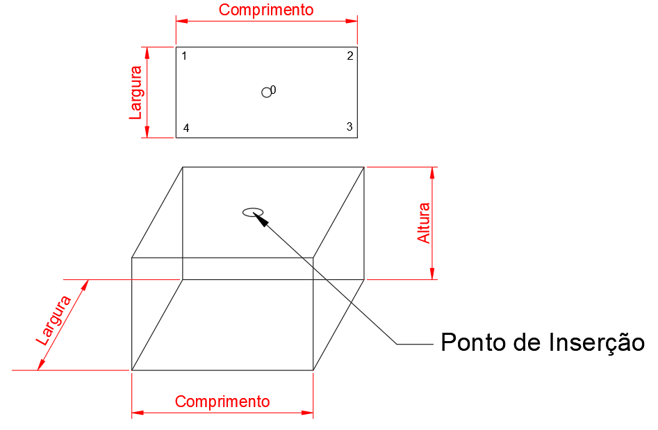
Number the vertices. For reference, look in the support folder for the DWG diagramacao.dwg
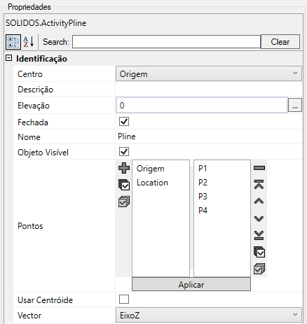
- Create points with the point creation tools
Note that the points need coordinates and they are written in the Properties frame
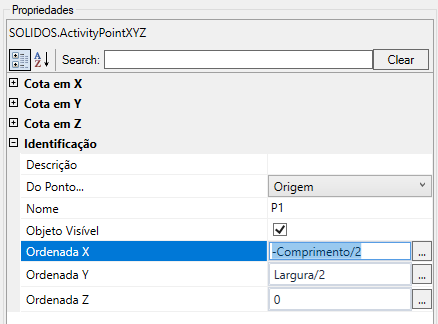
Note how the coordinates of the points relate to the device properties (width, height, length)
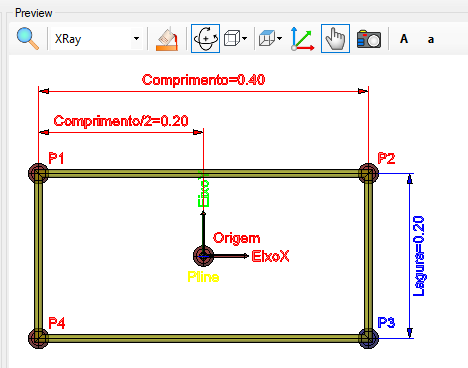
Note that it is possible to show dimensions in the preview, enabling in the point properties frame:
- Create the
Closed polyline that will be extruded. Note the order of points to be selected, the elevation it must be at and the fact that it is closed so that it can be extruded
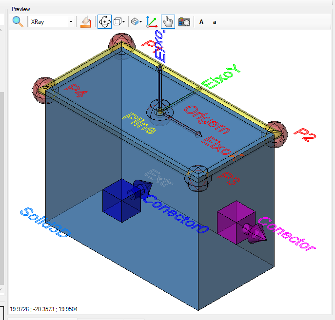
Notice how it looks in the preview:
Use the preview buttons to zoom in, change view type
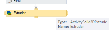
- Use the tool from
Extrude to create the parallelepiped
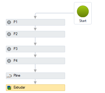
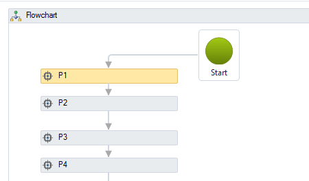
Note the lines that interconnect the "little boxes", they indicate the next step. Try clicking one and deleting. Try hovering the mouse over a
of the dot boxes and observe the small rectangles that appear around it:
Click one of them and drag it over another box

Note that it needs a "figure", which is the polyline and needs a height
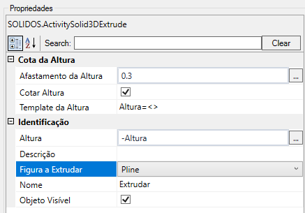
Note that height can be negative. By the way, why would the height be negative? Or, the user should write
a negative value in the "Height" property? Does that seem reasonable?
- Noticed that the construction process created a series of points, polyline that do not necessarily have to be drawn on the
Model Space from AutoCAD?
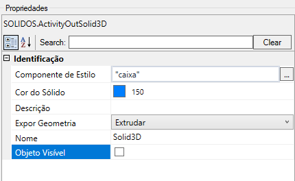
Use the tool
Expose Solid, so SOLIDOS knows what you want drawn
- What is this solid for? Is it a Box? What family does she belong to?
What is a family? A family serves to filter between various types of devices. Nodes can have:
- Link Box
- Manhole
- Sink
- etc
Enter this in the builder properties
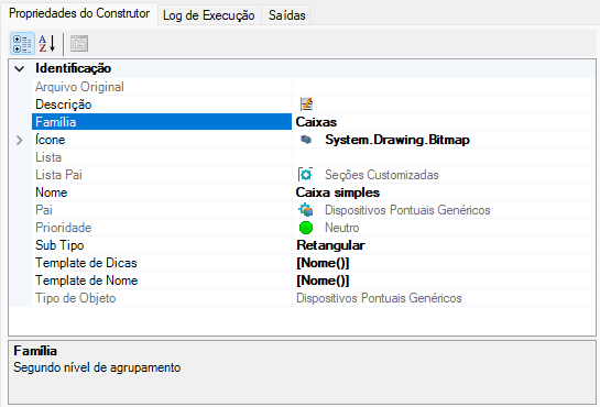
- What subtype is this box? Rectangular? square?
Who chose these names? What do they mean? Nodes can have boxes:
- Rectangular
- Trapezoidal
- Buried
- etc
Within the family, Nodes can have any number of subtypes.
Enter this in the builder properties
- What is the name of this device? Describe it in the "Description" property
- Did you notice that the device may have an icon for better identification on the program screens? Look at the rest of the icons on the Constructor interface
- Will this device connect to other devices?
What is the appropriate place in it for this?
What kind of devices can connect to it? Nodes must not connect the central bed ditch in the position where
Nodes normally connect the pipes and vice versa
Use Connectors to indicate this to the device
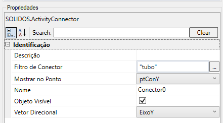
Note that the connector needs a point to be located:
- Should properties only have certain values? A list of them perhaps, or a range of valid values?
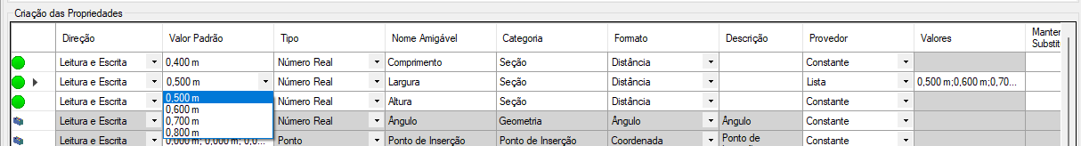
Look at the frame Creating Properties and configure this in the column Provider
- What units of measurement will you use? Length, Width and Height are "distances", usually measured in meters
- Don't know what "TrenchHeight" is? Have you looked through all the help on Required Properties?