SOLIDOS Modeler - Expose Solid
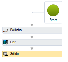
 Expose Solid - exposes a solid created in the model, so that it is actually drawn in the project:
Without this activity, it is not possible to add the model to the BOM and if any device has already been released using a model without
exposed solids, it will "disappear" from the project.
It will not be deleted, it will still be possible to edit its properties, but it will not appear.
The Expose Solid activity has the following properties:
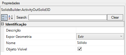
- Identification
- Name - name of the activity
The solid name must follow the naming rules
- Expose Geometry - name of solid to expose
- Style Component - Name of the style component
If empty, it will be the name of the geometry
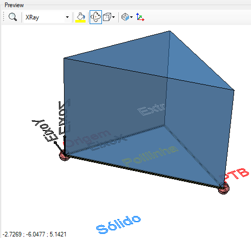
- Object Visible - indicates whether or not the point should be drawn in the preview
- IFC
In the modeler, click the
 IFC View button to see how the exposed solid will be drawn in the IFC file when exported using the SIFCEXPORT command.
- Distance Tolerance - Has the greatest impact on the mesh. It is especially useful for achieving high element density in areas of sharp curvature
- Angle Tolerance - Most useful for complex surfaces with "nodes" or abrupt changes in direction
- Maximum Node Spacing - Primarily used for flat surfaces, as it is the only way to ensure the surface is subdivided into more than one element
- Maximum Initial Subdivisions - A coarser granularity control that affects initial discretization
- Maximum Aspect Ratio - Controls the maximum width-to-height ratio for a 2D mesh element
These controls help quantify and shape the generation of elements in the mesh:
- Interior Density: The density of elements inside the mesh should accurately reflect the control settings (such as distance tolerance), except in cases of curvature Extreme
- Boundary Density: The density of elements along the surface boundaries can be much higher than requested due to shared nodes with adjacent faces
- Priority: Depending on the surface type, it is often necessary to define only one control to achieve the desired result. For example, on tight curves, Distance Tolerance is the most important
If the text gets too big/small, or the sphere that represents the point gets too big or small, use the buttons ( A, a,
 ,
,
 ) at the top of the screen to change the preview
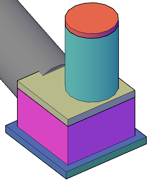
Note, a device can be composed of more than one exposed solid! A manhole, for example, may have:
- Lid (cast iron)
- Chimney (reinforced concrete tube)
- Slab or cone (reinforced concrete)
- Body (masonry, concrete, structural block)
- Floor (reinforced concrete)
Therefore, these components can be drawn with different styles:
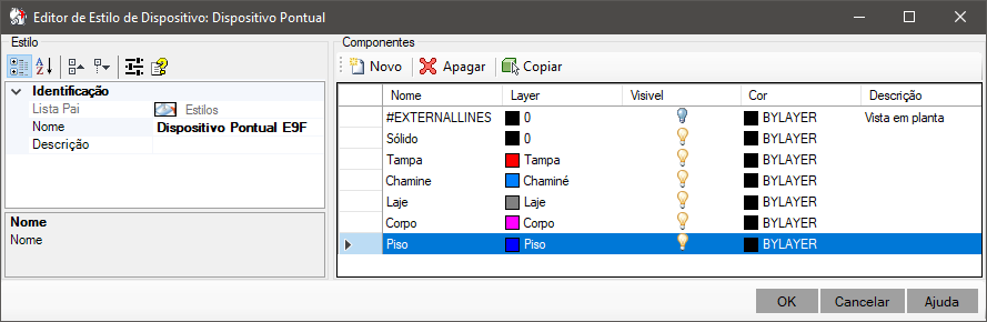
For the style to be effectively applied to the component, make sure that the Name property of the Expose Solid activity is the same as the name of the component.
component in the style (use the button
 Copy in the image above).