Common Columns
For the calculation, we have several columns in the spreadsheet.
If you cannot read and interpret the name, stop the mouse on the column name and the description will be given of it.
Here are explanations of what they are:

Optionally, instead of showing the column names with codes, you can
choose to show the descriptions.
To do this, click:

Thus, the descriptions of the columns will appear directly on the column headings.
Here is a list of columns and their descriptions:
REFALIN
reference alignment structure.
Affects the value shown in column station (ESTACA)
To change this, double-click the cell and choose an alignment.
SUMP
Specifies the sump depth, or the vertical distance from the invert of the lowest pipe attached to the structure to the inside bottom of the structure:

Sump is:
SUMP = CM - CFM
PVEXIST
whether a structure is existent or not.
If it is marked as true (the box is
checked), the columns CTM,
CFM, PROF, PV will be read-only.
The Minimize button will have no effect on this
structure if it is marked as existing.
TUBOEXIST
Reports if the hose is existent or not.
If it is marked as true (the box is
checked), the columns
CM, CD, INC., SUMP, DEG, BERCO,
TUBO will be read-only.
The Minimize button will have no effect on this pipe if it is marked
as Existing.
ESTACA
structure reference station.
Use the command  CALIN
if required, to associate an alignment structure, or change the
reference alignment in REFALIN column.
CALIN
if required, to associate an alignment structure, or change the
reference alignment in REFALIN column.
The formatting of this column depends on how the item is set in "Toolspace / Settings / Drawing Settings / Ambient Settings / Station " in Civil 3D:

PV
Upstream structure
This column controls the structure section at pipe start point, use it to change this.
Note: that the list only structures available in
Parts list appear.
To change this, double-click the cell.
Will open a box where you
can choose another structure section:
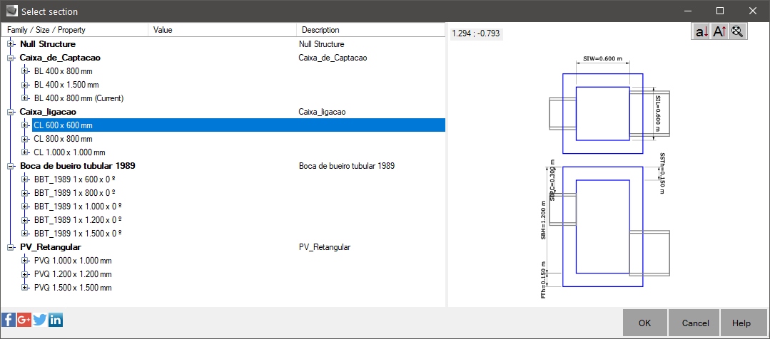
Values written in red indicate that the section of the structure is not big enough for all pipes connected
or that the upper generatrix of a pipe is higher than the cap itseLAMINA.
If the structure has
frame, the cover is
slab that sustains it.
Tip: To read the values of the current section, you can use this feature to display these values, expanding the item
highlighted in the image.
The maximum size should be in structure section rules.
TUBO
It is the pipe section.
This column controls the section of the pipe, use it to change this.
Note: that the list appear only pipes available
in Parts List.
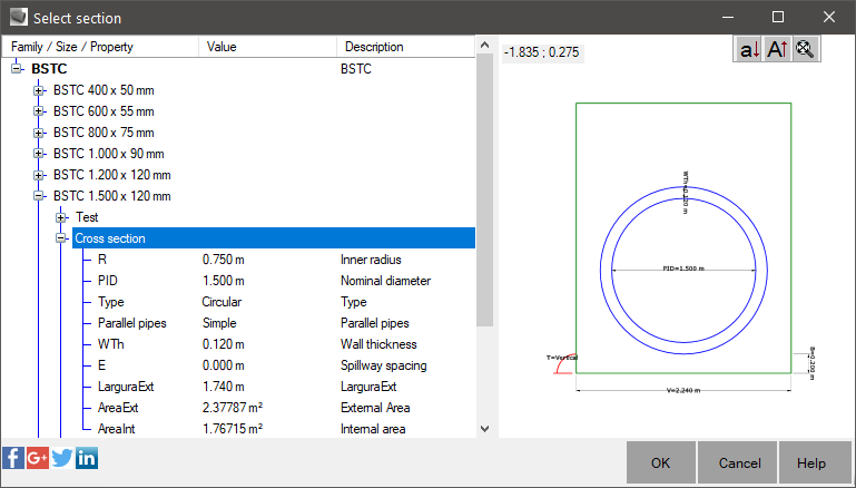
To change this, double-click the cell.
Will open a box where you
can choose another pipe section:
Changes in this column reflect changes in all sections downstream of this, to maintain compatibility of the pipes.
If the option to resize the structure is enabled under parameters,
structures will be made compatible.
For this to work, you must configure the
structures size rules correctly.
TRS
Reference surface of the pipes.
Will be used to calculate the cover of the pipe and also the excavation.
If a
surface is not selected, an error will be shown in the RULES
column.
PVS
Reference surface of the structure.
Will be used to calculate the CTM value.
Note: that changing this column does not produce changes in the
sump elevation (CFM).
If a surface is not selected, an error will be shown in the RULES
column.
NOME
Name of upstream structure
NOMEJUS
Name of downstream structure
RULES
Reports the number of errors on the line.
If you stops the mouse over a cell of this column will be aware the errors that occurred:

X
Start Structure X ordinate.
It is not necessarily the same as the beginning of the pipe, as it may not be positioned at the insertion point of the structure.
See the CAJUSTA command help
Y
Start Structure Y ordinate.
It is not necessarily the same as the beginning of the pipe, as it may not be positioned at the insertion point of the structure.
See the CAJUSTA command help
CTM
Start Structure Rim Elevation.
CTJ
End Structure Rim Elevation.
CTMON
Surface elevation at structure location.
Informs the elevation on the reference surface of the pipe in position amount.
By replacing the reference surface, this value is changed.
Note: the differences between this value with CTM value.
CTJUS
Surface elevation at downstream structure location.
Informs the elevation on the reference surface of the pipe in the end structure.
By replacing the reference surface, this value is changed.
If you need to redefines the dimensions of the structures, because we changed the reference surface for example, select the
lines and change the menu Structures/Set elevations from surface :

CFM
Start Structure Sump Elevation.
CFJ
End Structure Sump Elevation.
PRFM
Rim to sump height.
Defined as:
PRFM = CTM - CFM
PRFJ
End Structure Rim to sump height.
Defined as:
PRFJ = CTJ - CFJ
PRFCM
Pipe start invert height.
defined as:
PRFCM = CTMON - CM
Use it to control the pipe start invert elevation or click the buttons on the display profiles:
Note: that these buttons will change the dimensions of the pipe
invert elevation.
In
then propagates the change to the dimension of the bottom structure depending on
is configured as the spread of fixes:

PRFCD
Pipe end invert height.
defined as:
PRFCD = CTJUS - CD
Use it to control the elevation of the pipe end invert height typing the value in this cell.
CD
Pipe end invert elevation
CM
Pipe start elevation.
It can be equal to CFM or not.
LAMINA
water height actual flow within the pipe.
Defined by:
LAMINA = H/DN
Where DN is the diameter or height of the pipe and H is the height of the water layer.
Values written in red indicate that the water height is greater than the maximum
water height, or the water height the pipe is higher than the upper generatrix of internal pipes that reach downstream structure.
DEG
Pipe drop.
Defined as:
DEG = CD - CFJ
This column is controlled by pipe drop rule.
Red values indicate greater than the maximum or lower than a minimum.
If higher values are observed, the cell appears red.
In parameters frame you can enable the pipe drop control.
So if you have a
snippet big drop, the value of the end pipe elevation (CD) will be changed.
INC
Pipe slope
Defined as:
INC = (CFM - CD)/EXT
Note: that this value cannot be negative.
Or even better, cannot be less than the minimum or greater than the maximum value defined in rules.
In the parameters frame you can enable the slope
control.
So if you have a snippet slope large or small, the value of the end
pipe elevation (CD) will be changed.
EXT
2D Pipe length, center to center.
Note: that is not necessarily equal to the distance between the structures.
Values in red indicate that the rule length was violated.
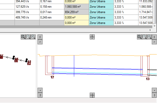
INTERF
Shows the number of interference in the pipe.
In the figure, we see in plan and
profile, there is interference with other pipenetwork (in red):

COBMIN
Shows the minimum cover of the pipe.
Values ??in red indicate that the cover rule was violated.
In the picture we see that the minimum cover was violated:

COBMAX
Shows the maximum cover of the pipe.
Values ??in red indicate that the cover rule was violated.
NMAN
Manning coefficient.
Manning's roughness coefficient.
Typically 0.015 for concrete pipe and 0.009 for PVC pipes
You can set this value in the Parts List , so the launch pipe, the value is applied to the released pipe.
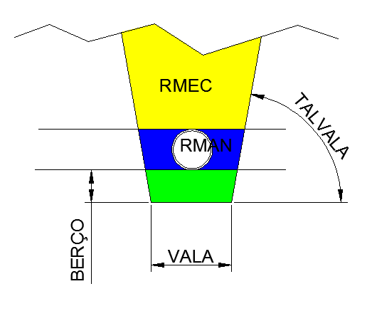
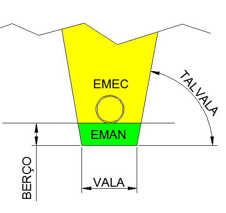
VALA
Ditch width.

To calculate the volumes, are calculated hatched areas in yellow, blue
and green, beyond the area of the outer pipe.
The values for each section can be seen in table
that appears when you click the button  in the preview section, or in the menu
Pipes / Show results of the excavation:
in the preview section, or in the menu
Pipes / Show results of the excavation:

This worksheet shows the result of an excerpt only.
To view all
the excerpts, go to menu File / Export.
Are calculated cross-sectional areas of a number of sections on the pipe and applying the method of the sections.
The away between the sections is defined in parameters frame.
TALVALA
Ditch walls slope.
You can enter values as follows:
-
3:1 y:x
-
Vertical
-
1:3 x:y
-
90 deg
-
1.57 rad
BERCO
Cradle of ditch.
Height is to be excavated beneath the outer generatrix of the pipe manually in order to regularize the bottom of the trench to lay the mattress of gravel.
ESCORA
Area shoring of the trench.
Is the area shoring

ESCORA= SUM (DISTSECOES * (LE1 + LE2 + LD1 + LD2)/2)
RMEC
Mechanical refill.
Is the value of the volume that can be covered onto the pipe in the trench.
Not used
fill factor, this values are GEOMETRIC.
RMEC = SUM (DIST(i) * (AreaAterroMec(i) + AreaAterroMec(i-1)) / 2)
If the pipe is within existing and the item "Calculate excavation"
is marked as False, this value will be zero.
EMEC
Mechanics excavation.
Is the value of the volume that can be excavated.
EMEC = SUM (DIST(i) * (AreaCorte(i) + AreaCorte(i-1)) / 2)
The upper surface is the pipe reference surface (TRS ).
If the pipe is within existing and the item "Calculate excavation"
is marked as False, this value will be zero.
RMAN
Coating Manual
EMEC = SUM (DIST(i) * (AreaHtubo(i) + AreaHtubo(i-1)) / 2)
The volume value is to be covered by hand, between the walls of the trench and the pipe wall where it is not machinery.
Fill factor is not used, the values are GEOMETRIC.
The pipe section is discounted.
If the pipe is within existing and the item "Calculate excavation"
is marked as False, this value will be zero.
EMAN
Manual Excavation
EMAN = SUM (DIST(i) * (AreaBerço(i) + AreaBerço(i-1)) / 2)
Is the value of the volume to be excavated manually or regulated manually.
Corresponds to the area marked in green:
If the pipe is within existing and the item "Calculate excavation"
is marked as False, this value will be zero.