The Design tab was designed to facilitate small edits on the network, as any change is automatically applied to the drawing.
The SCALC command screen does not apply the changes until you click the OK button. Thus, changes to the Model Space are only applied at the end. If you use the Design tab, Model Space is modified all the time and this is a slow process. Also consider that SOLIDOS makes use of labels and tables. There is no need to update these items while calculating a network. It also takes processing power.
After the net was launched, we are still not sure about the diameters, covers or even the slope of the tubes. Do not do it makes no sense to allow the calculation engine to be switched to automatic during this phase, as it will calculate wrong values. To enable/disable the automatic calculation, click the
During hydraulic adjustment, calculating the excavation trench is unnecessary. This is a calculation that consumes a lot of computer resources. Leave to enable this calculation only at the end of the hydraulic project, except for situations where there is very high trench excavations, in which case it can justify changing the diameters, or even the number of lines in a stretch. Disable trenching for all devices at once by clicking the
Again, it is a feature that is currently unnecessary. Each row selected in the worksheet forces Zoom into Model Space, which sometimes requires an REGEN operation, which can be slow. Use when the net is almost ready, needing only small adjustments in pipe drop or sump, for example, to turn off the automatic zoom, click the button
When you select many pipes at the same time, the program needs to draw them all in the preview and that takes time. In the initial adjustment, you don't need the preview, since we know what will change before calculating. Click the button (
Here it is important to have a well-defined
Although it is possible to change diameter directly in the section properties category, avoid doing this. Always prefer the property Object / Section, because when changing the section for this property, we guarantee that we change not only the diameter, but also the rules, styles, in addition to the layer, dimensions and characteristics of the trenches that are excavated
It is common to adopt a minimum cover depending on the pipes available for the project. You can do this in the worksheet by selecting all the pipes at once and changing the value in the properties frame:
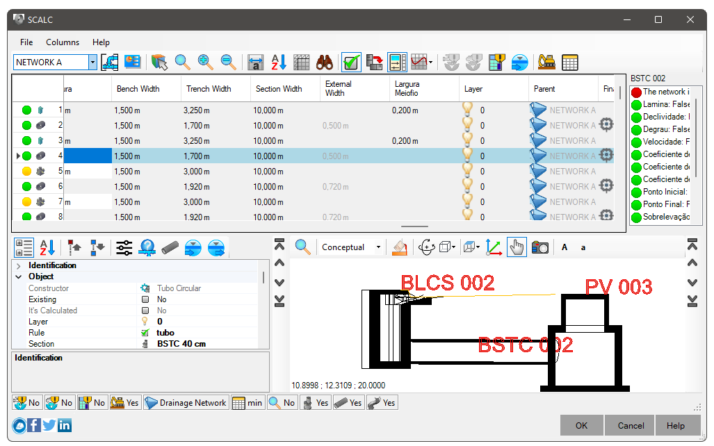
This way you ensure that most of the network has a minimized trench excavation, of course, there may be pipes against the flow and in this case,
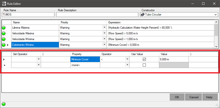
Defining the initial and final cover can cause some pipes to have a slope lower than the minimum slope adopted. In gravity networks this is a problem, so select pipes whose slope is low and apply the minimum value
During the cover and slope adjustment process, it is normal that some punctual devices (manhole, manhole, connection box) cannot be modeled. In general, this occurs due to absurd elevations in the tubes, for example, elevation of the tube above the elevation of the cap. These errors will be corrected in time, when the tubes respect the cover and slope
Note that so far, we have not been concerned with point devices. Don't worry about pipe drop or sump for now, they will be adjusted later.
First, it is necessary to ensure that the "smallest network", or "least expensive network", meets the flow with minimum diameters, covers and slopes. Use the
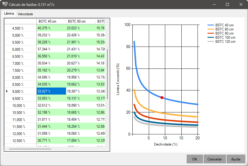
This saves you time instead of "trying out" every possible variation manually. Note that drainage networks there are usually many connecting sections between the manhole and the culverts. In general, 0.5% slope can cause low runoff velocities. Then look at what minimum slope results in acceptable speed and stick with it. Try to modify as many pipes as possible, even though the calculation is out of date at this point, it's faster than fitting a pipe and calculating everything every fit
After having adjusted the minimum slopes, force the network calculation by clicking the
Note, for this to work, you must have created a minimally smart modeler. What does that mean: He has to be able to interpret the elevations of the pipes in order to limit the elevation of the bottom of the box.
If you use the manholes that I make available in the plugin, you may have noticed a box in the flowchart saying "Processa Altura":

Study the flowchart and you'll notice that even if the user puts Height=0.1m, the program will change to, say, 1.5m, because there is a pipe (with minimal cover) that limits it to the minimum height
Like the culverts, the manhole also checks the connected pipes and it can even force the chimney size, depending on elevations maximum and minimum values of the connected pipes. Note that this behavior needs to be defined in the modeler, just like the culverts. Note that the body (or balloon) of the manhole is not the full height, as we need to account for the chimney (or neck)
Depending on the project, a minimum step is required in order to form a sand accumulation box in the manhole:
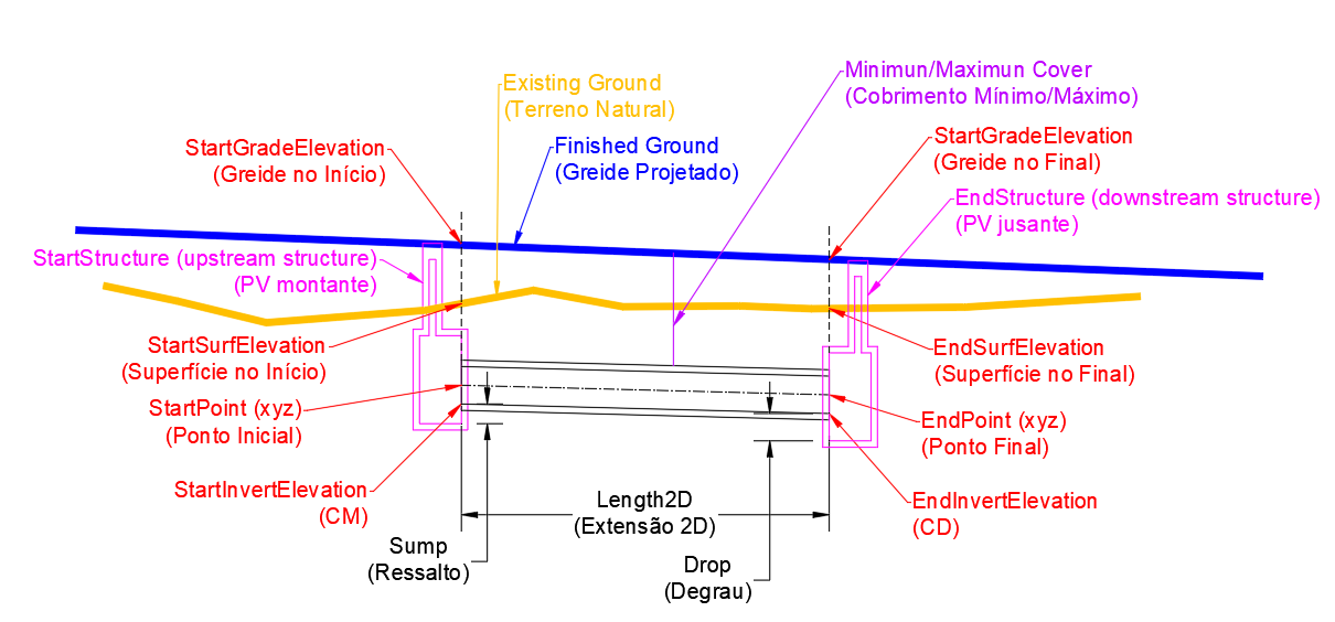
In the pipe modeller, what happens when you change the step or step? Watch:
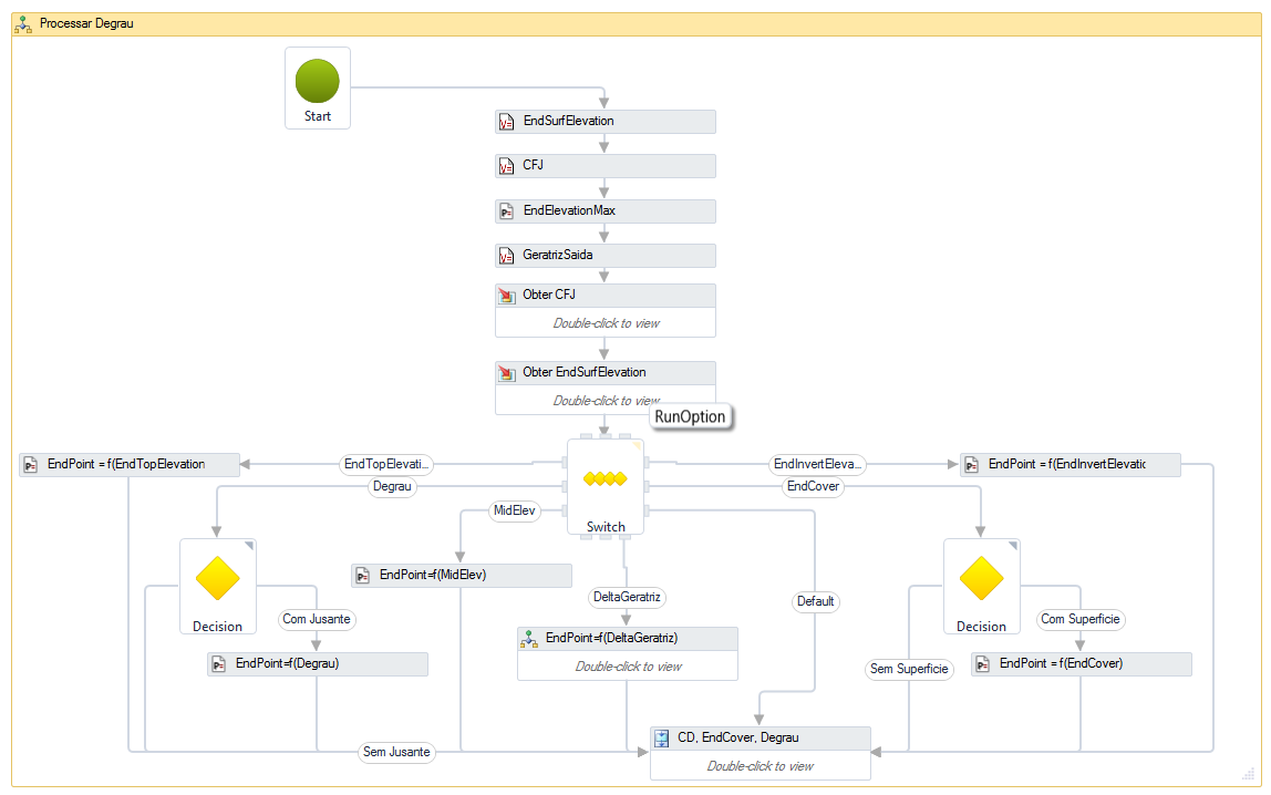
This is the flowchart that changes the elevation of the endpoint of the pipe ( EndPoint) as a function of the elevation of the pipe drop, depth of downstream, final cover, end invert elevation, end top elevation, etc. So keep in mind that it is necessary to study the devices that will be used, before placing them in the network, so in this script we suggest changing the initial and final elevations of the pipe depending on the coverage and not because of the drop/sump and also because of this, we suggest changing the height of the culverts and manholes after having adjusted cover and slope
- Turn on network preview in profile mode by clicking the button (
 ,
, ,
, ) at the top of the screen. Note that when selecting more than one pipe, you can see an overall profile of the network
 - Turn on trench calculation to check trenches
- Calculate the net one last time, to validate the rules (speed, blade, step...)
- Observe if all the applied rules were satisfied, that is, all the balls are green:
 or yellow
  .
Take into account the guidelines for the meaning of these colors
- Click the OK button, so that the changes are applied
Note, this may be a more time consuming operation. To REGEN the Model Space AutoCAD needs to redo all device blocks, labels and tables.