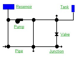
EPANET models a water distribution system as a collection of links connected to nodes. The links represent pipes, pumps and control valves. The nodes represent junctions, tanks and reservoirs. The figure below illustrates how these objects can be connected together to form a network:
In the picture, click:
 Reservoir - nodes that represent an external infinite source or sink of water to the network
 Tank - are nodes with storage capacity, where the volume of water stored can vary over time during a simulation
 Junctions - are points in the network where links come together and where water enters or leaves the network
 Pipes - The pipes lead the water from one point to another in the network. EPANET assumes that all pipes are full at all times
 Pumps - Pumps are devices that transmit energy to a fluid, thus increasing its hydraulic load
 Valves - Valves are used to control pressure or flow at a specific point in the network
In addition to these physical components, an EPANET project can contain the following objects that describe the performance and operation of a distribution system:
 Curves - are objects containing pairs of data that represent a relationship between two variables
 Time Patterns - collection of multipliers that can be applied to a quantity to allow it to vary over time
 Controls - instructions that determine how the network is operated over time
 Analysis Options