 STABLESTYLES
STABLESTYLES
STABLESTYLES
The command
STABLESTYLES creates and edits table styles for tables and reports
To use, call STABLESTYLES from the command line, menu, toolbar, in the Ribbon choose the style you want to edit:

On this screen you can:
 New - Create a new style
 Delete - Delete selected styles if not in use
 Edit - Edit the selected style
 Copy - Copy and edit the selected table style
 Pick - select on the model space an item that has the style you want to edit
A table style is actually a template for choosing columns, properties etc, for extracting data from devices, catchments or even networks. Below, an example:
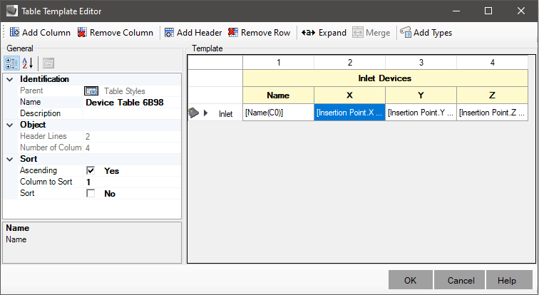
On the screen, at the top, you can see the following buttons:
 Add Columns - To add columns to the template
 Remove Columns Removes selected columns
 Add Header - to add lines to the header
 Remove Row - Removes selected rows, whether headers or data
 Expand - Expands the columns of the editor.
Note, it does not affect the resulting table drawn in CAD or exported
Expand - Expands the columns of the editor.
Note, it does not affect the resulting table drawn in CAD or exported Merge - Merges or unmerges the selected cells.
 Column Visible - toggles the state of the column:
Checked - means the column will be shown in the final result
Column Visible - toggles the state of the column:
Checked - means the column will be shown in the final result Unchecked - means the column will not be shown in the final result
 Add Types - Add element type filter row in table

 Filter - Creates/Edits a filter for the selected line

 Sum Row - Adds a calculated data row that can sum quantities


 Hydraulic Sections in design - makes it possible to list the results of the tab Hydraulic Sections
for the beginning of the project (dimensioning). applies to
Hydraulic Sections in design - makes it possible to list the results of the tab Hydraulic Sections
for the beginning of the project (dimensioning). applies to
 longitudinal gravity devices only
 Hydraulic Sections in design - makes it possible to list the results of the tab Hydraulic Sections
to the end of the project (verification). applies to
longitudinal gravity devices only
Hydraulic Sections in design - makes it possible to list the results of the tab Hydraulic Sections
to the end of the project (verification). applies to
longitudinal gravity devices only
 Points - makes it possible to list the points of
 longitudinal devices
 Input Device - in styles of
 device tables, when the template line shows information for
 linear devices or
longitudinal devices, it is possible to show information about the device
plugged into device input
linear devices or
longitudinal devices, it is possible to show information about the device
plugged into device input
 Output Device - in styles of
device tables, when the template line shows information for
linear devices or
longitudinal devices, it is possible to show information about the device
plugged into device output
Current Device - in styles of
device tables, when the template line shows information for
linear devices or
longitudinal devices, and the cell has information about the input device
or output click to be able to add linear device properties
Output Device - in styles of
device tables, when the template line shows information for
linear devices or
longitudinal devices, it is possible to show information about the device
plugged into device output
Current Device - in styles of
device tables, when the template line shows information for
linear devices or
longitudinal devices, and the cell has information about the input device
or output click to be able to add linear device properties
 Excavation - in styles of
device tables, when the template line shows information for
linear devices or
longitudinal devices, and the cell has information about the excavation
from the device ditch
Copy Line - Clones the current property row, making it possible to choose another type of item
Excavation - in styles of
device tables, when the template line shows information for
linear devices or
longitudinal devices, and the cell has information about the excavation
from the device ditch
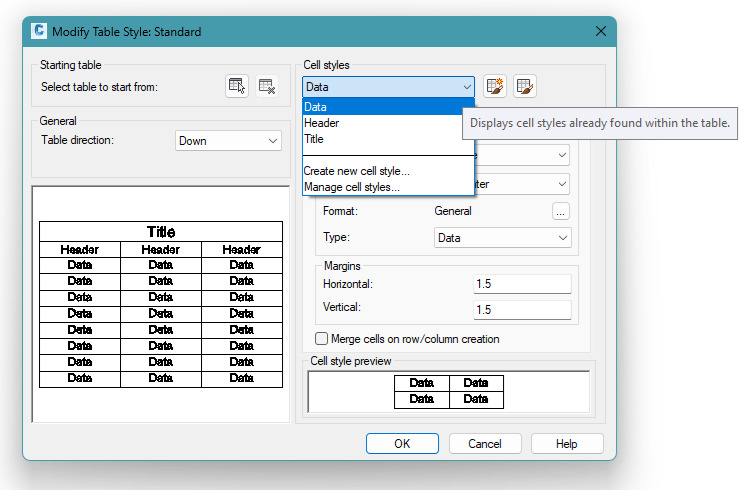
Copy Line - Clones the current property row, making it possible to choose another type of item New!!!: A table in AutoCAD can have a title, header, and data. These can have different styles, as shown in the TABLESTYLE command, native to AutoCAD:
After choosing an object type, it is necessary to add the macro that defines the property and formatting expected for it. To do this, double-click on the cell:

The Macro Editor will open:
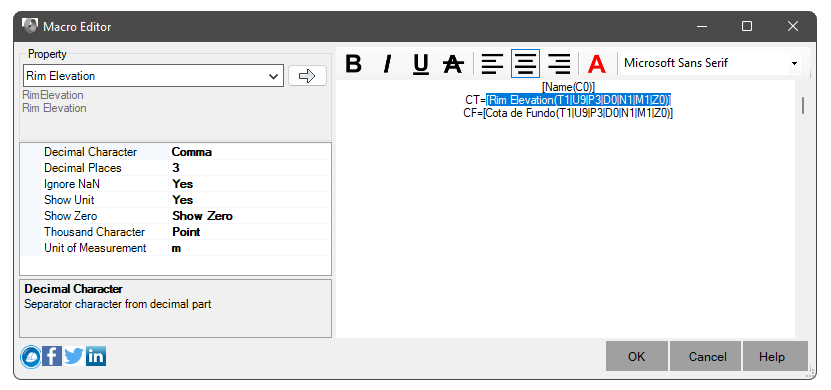
Choose the property, formatting and click the button

Note: Device tables may require cross-referencing. This happens when linear device data does not show data referring to point devices.
For example: Nodes want a table of pipes that shows data from the PV insertion point, or even data from its Hydraulic Design (precipitation, contribution area, etc).
In this situation, use the buttons
Input Device,
Output Device. You will notice that the cell icon will change. This means the properties will be read
on the upstream or downstream PV, not on the pipe itself.
Note: Linear devices (pipes, gutters, etc) when they have excavation calculated, can also show this data in the table.
In this case, it will be necessary to click the button
Excavation and add any columns you want.
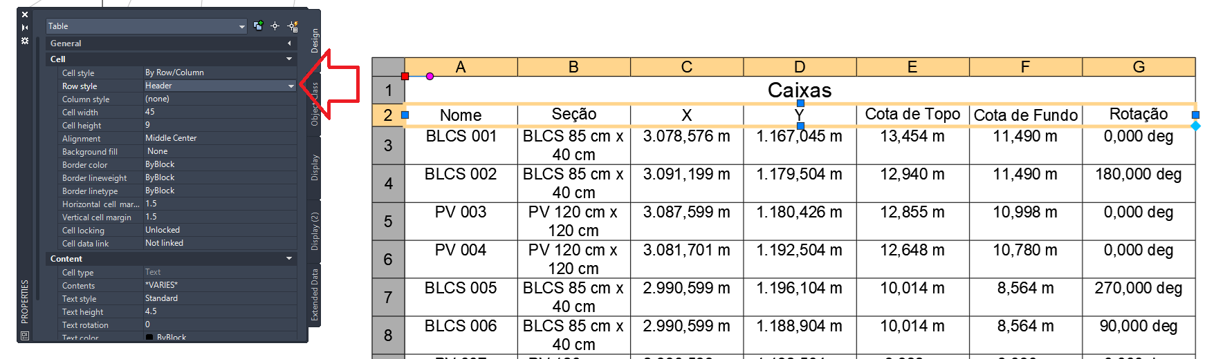
To exemplify the two situations above, consider the style below:

Columns and 5 show upstream and downstream PV data respectively, while columns 1, 2 and 3 show pipe data. In the row below, columns 5, 6 and 7 show data from the excavated trench. Note that the excavated trench has several sections. Therefore, multiple lines are added. A possible result of the above style:

Note: When creating a table, you will be asked to select the elements that can be included in the table listing.
If the type is not present in one of the rows of data in the table template, or is not a type
child of the types listed in the template, it will be ignored.
If it matches more than one row of data, the element may appear more than once in the resulting table.