Device Projection
A device projection is a profile or section view of the device.
This view needs to be drawn over a ProfileView or a SectionView.
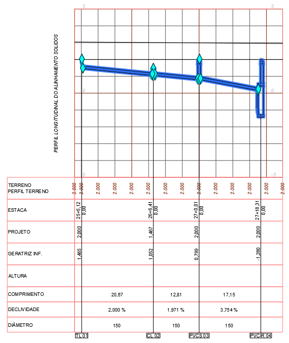
An example of a profile projection of a sewage network:
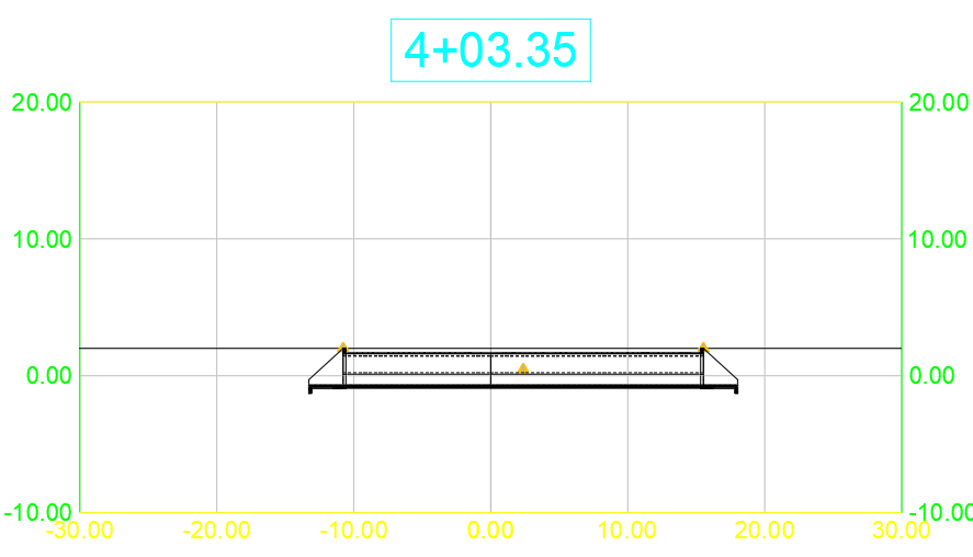
Another example, of a simple manhole:
 Note: Devices are represented according to the style applied.
In this style, you can mark which items/layers should appear:
- External contour
- Hachures
- Central Lines
- Internal Lines
- External Lines
- 3D solid
 Important: the projection is not like PipeNetwork.
It depends on the position of the alignment or Sample Line.
In the device projection, you can still see some
 Grip Points, for editing insertion point elevation, background elevation
of the device or what the template includes for profile/section editing.
The projection has the following properties:
- Identification
- Name - Device name
 Note: renaming the projection implies renaming the device
- Description - Device description
Sometimes it is necessary to make some type of note on the device, informing something that does not have a specific property for such, for example: a wing may be silted and this information is relevant in the project
- Parent List - Device name associated with this projection
- Object
- Style - name of the style in which the projection is drawn
- Layer - name of the layer on which the projection is drawn
- Network - name of the network to which the device of this projection belongs
- View - name of the Profile View or Section View in which the projection is drawn
- Projection Side - Side to which the viewer looks when positioned on the cutting plane axis
If the device is on the right side of the alignment, without crossing it, if the projection is set to the left side, it will not be
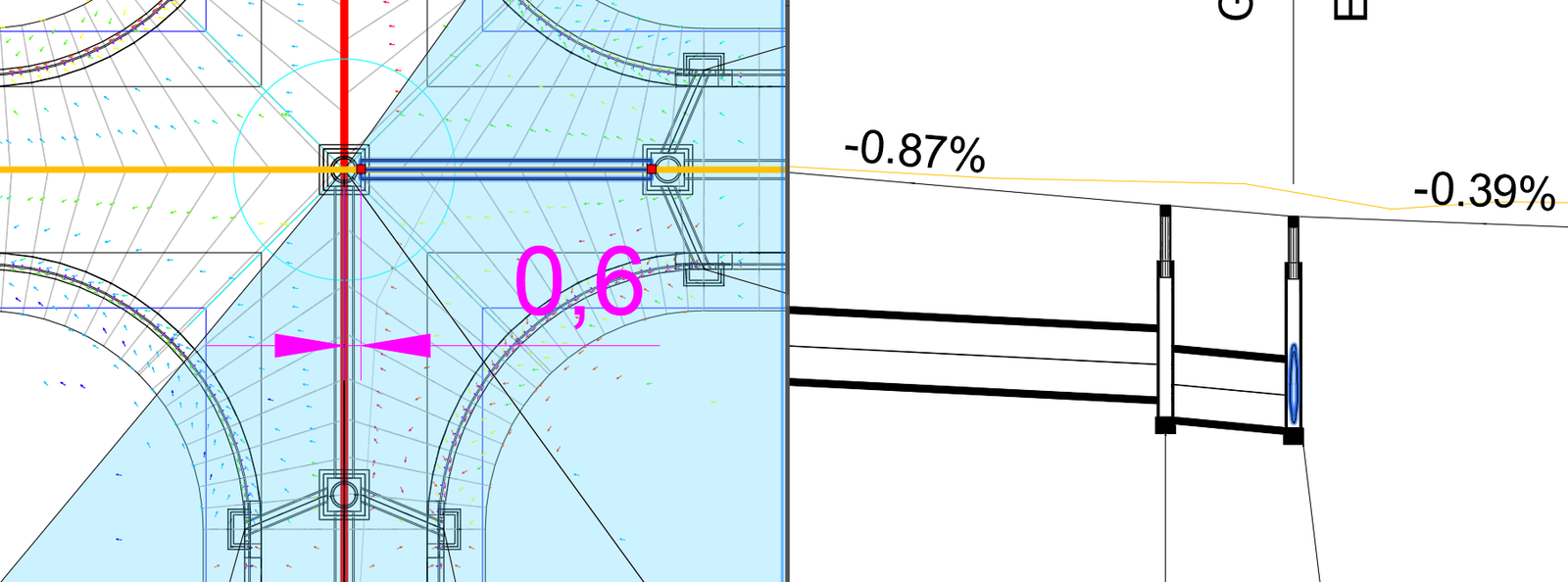
visible. Obviously it also depends on the projection style. In the drawing below, the pipe selected in the left window is projected in the ProfileView in the right window, but does not cross the red alignment, which runs south-north. So the projection is only visible to the observer who is positioned at the intersection of streets looking to the right
- Maximum View Distance - maximum view distance to where the device is represented
Above this value, the projection is not drawn
watch the drawing the below:
In red, in the left window, we have the street axis and in the right window we have the ProfileView of this axis. The pipe selected in the plan is projected in this view, considering a maximum distance of 0.61, which is slightly greater than the half-width of the manhole (0.60):
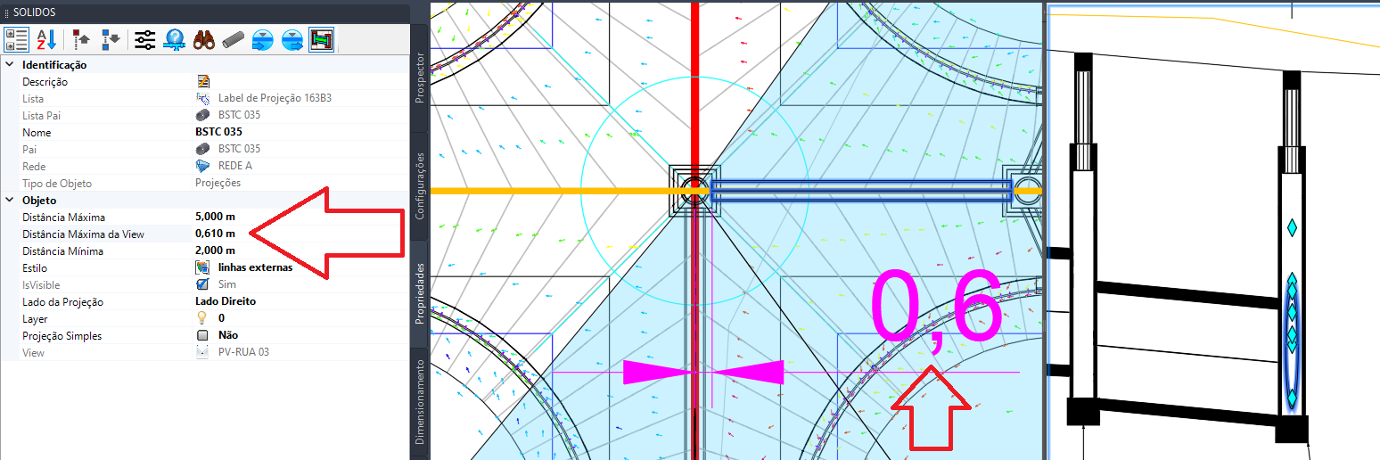
Note that the projection of the pipe drawn horizontally will be represented in cross section in relation to the red alignment, while the pipe drawn vertically in the left frame, is represented in longitudinal section in the ProfileView.
If we don't limit the maximum distance, it will represent this way in ProfileView:
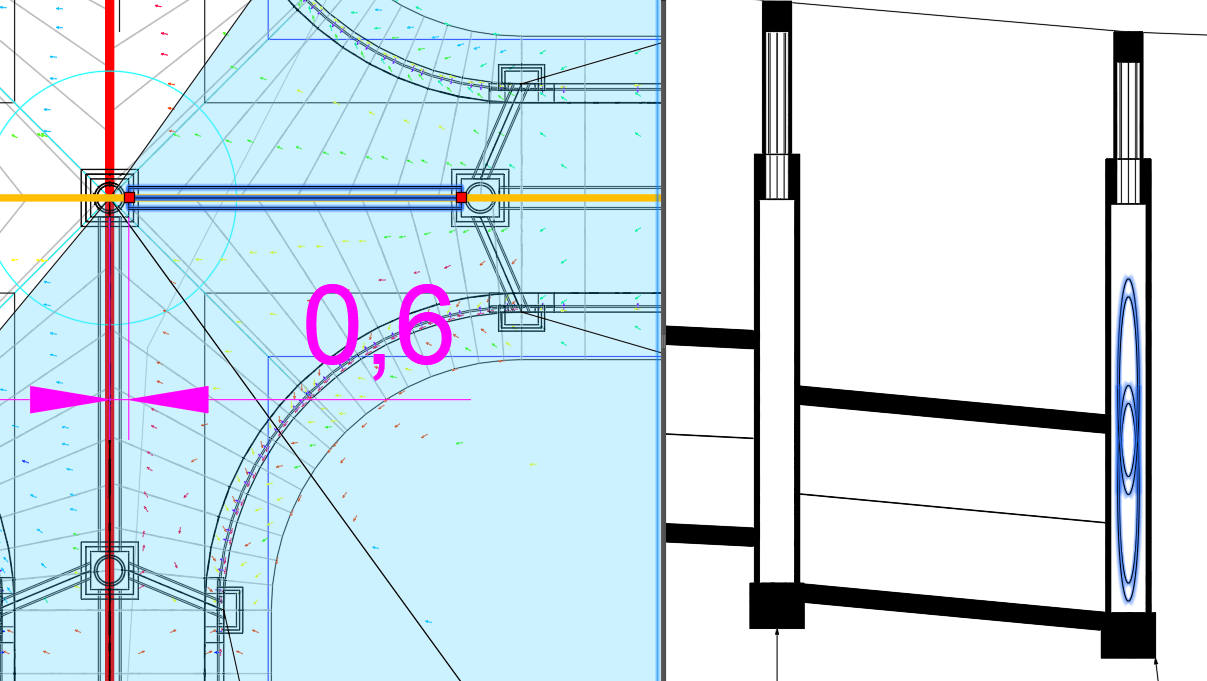
Note the projection of the selected tube. We now see the near face and far face of the view "overlapped".
The commands for editing projections are:
-
 SPROJECTION - creates the projection of selected devices
-
 SPATHPROF - creates the projection of devices contained in a path between two devices
-
 SPROPS - to edit projection properties
-
 SPROPSDISP - to edit the properties of the device that generates the projection
-
 SVIEWPROJECTIONS - to edit the projections of a ProfileView or SectionView


![]() Note: Devices are represented according to the style applied.
In this style, you can mark which items/layers should appear:
Note: Devices are represented according to the style applied.
In this style, you can mark which items/layers should appear:
![]() Important: the projection is not like PipeNetwork.
It depends on the position of the alignment or Sample Line.
Important: the projection is not like PipeNetwork.
It depends on the position of the alignment or Sample Line.
![]() Grip Points, for editing insertion point elevation, background elevation
of the device or what the template includes for profile/section editing.
Grip Points, for editing insertion point elevation, background elevation
of the device or what the template includes for profile/section editing.


