Additional Processing Flows – Variable Ditches
Certain linear or longitudinal structures do not maintain a constant cross-section along their axis.
Consequently, the excavation ditch cannot have a constant profile either, as this would result in inconsistent values with the structure itself.
Consider the example of rectangular channels with variable height, such as the Canal Retangular com Grelha Metálica (VALE standard):
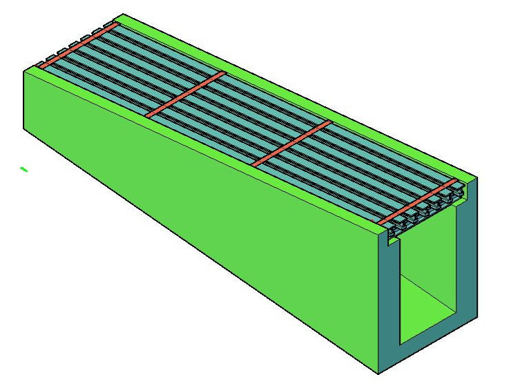
Typically, this type of structure features a horizontal grade at the top, as it is used in yards and track crossings;
Thus, it is necessary to construct the section with a variable height—ranging from a minimum to a maximum—to ensure proper flow.
Although the variation is slight in this example, there may be situations where the height difference is significant, justifying the inclusion of this extra flow.
To add this extra flow to the modeler, follow these steps:
- In the modeler flowchart, include an IF or a Switch:
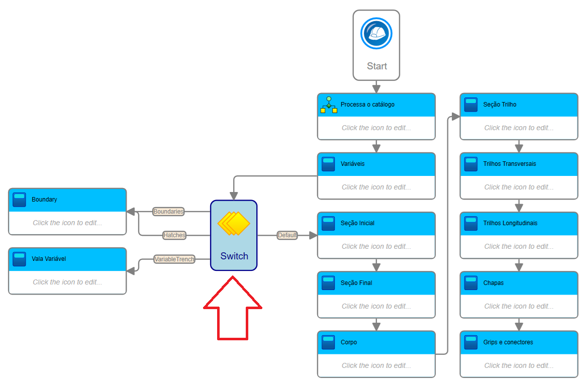
- If you choose the Switch, enter the following in the Choice Expression:
ExtraFlows.ToString
In SOLIDOS, the Switch operates using strings
- If you choose an IF, the expression will be:
ExtraFlows = ExtraFlows.VariableTrench
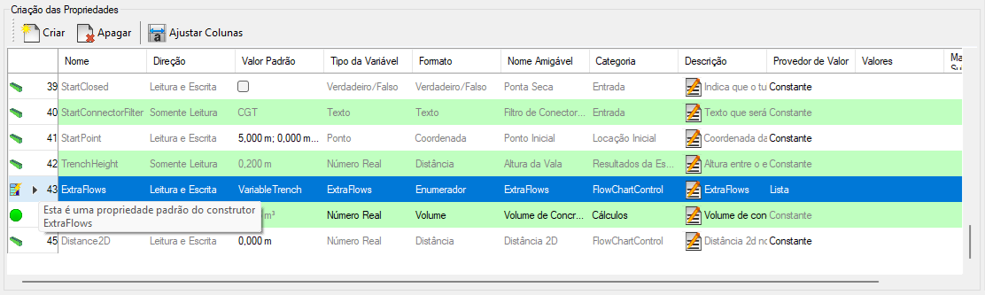
In the properties panel, ExtraFlows is a standard modeler property; its value is an enumerator of the type SOLIDOS.ExtraFlows:
- Add a Sequence to the flowchart and, within it, add a Set Parameter activity for each of the trench variables:
- Length - total length of the structure
ccomprimento = StartPoint.Distance2D(EndPoint)
- Height to Cover (CoverHeight) - Distance from the device's axis to the top of the typical section
CoverHeight = StartHeight + (EndHeight - StartHeight) * Distance2D / length
- Trench Height (TrenchHeight) - Height between the axis and the top of the bedding
TrenchHeight = FloorHeight
- External Height (OutHeight) - Total height of the typical section
OutHeight = CoverHeight + TrenchHeight
- Trench Offset (DisplaceDitch) - Shifts the trench axis relative to the device axis
Positive values ??shift to the right, and negative values ??to the left
DisplaceDitch = 0.0
- External Width (OutWidth) - Total external width of the typical section
OutWidth = Width + 2 * WallThickness
- External Area (OutArea) - Total external area of ??the typical section
OutArea = OutHeight * OutWidth
Obviously, these equations may vary depending on the typical section.
For this example, a rectangular section was considered, where the internal height varies and the axis defining the section is fixed at the top of the internal floor:
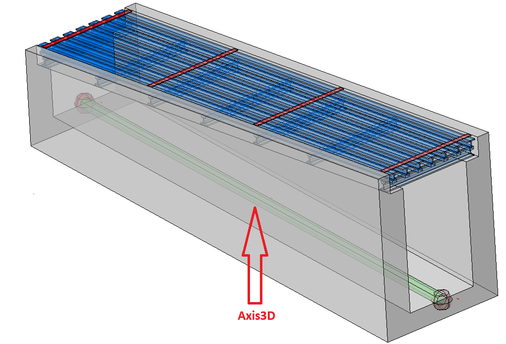
For this example, CoverHeight is the key variable. It must be recalculated for each reported distance
- For each distance reported by the excavation calculation engine, these variables must be recalculated; therefore, understand how they work:
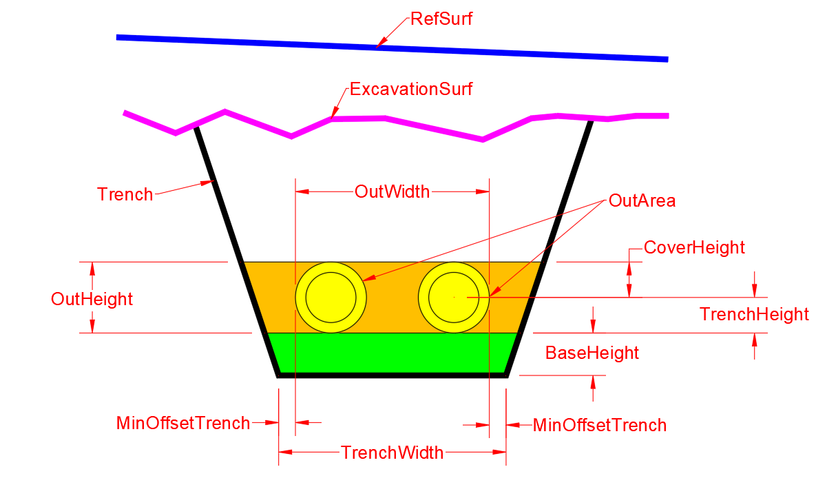
Or, more specifically for the example:
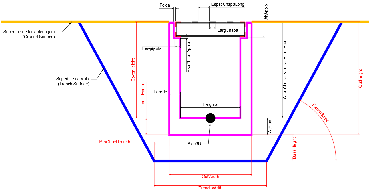
Note that the typical section measurements (black) are created by the user and can have any name.
However, the excavated trench measurements (red) are mandatory measurements
- Observe the formula used to calculate CoverHeight:
CoverHeight = AlturaIni + (AlturaFim - AlturaIni) * Distance2D / comprimento
Here, the Distance2D variable is a standard property of the modeler that appears in the properties panel:
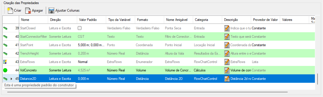
This property only takes effect in this extra flow; it is ignored in the others
At the end of the process, observe the results for an inserted component:
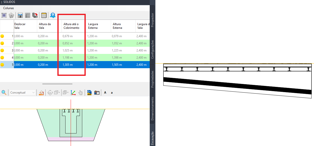
In the image, the highlighted column is Cover Height (the CoverHeight property), which varies along the component because the component's height varies.
Open the Vale catalog and look at the ./Support/Vale.dwg file; within it, open Linear Gravity Devices / Canal Retangular com Grelha Metálica - CGM (VALE) to understand the property layout as well as the extra flow demonstrated here.