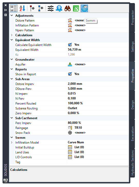
 SWMM - Subcatchments
Subcatchments are hydrological units of land whose topography and drainage system elements direct surface runoff to a single point of discharge.
The user is responsible for dividing a study area into the appropriate number of subcatchments and for identifying the exit point of each subcatchment.
The discharge points can be nodes of the drainage system or other Subcatchments.
Subcatchments are divided into permeable and impermeable subareas.
Runoff can infiltrate into the upper soil zone of the permeable subarea, but not through the impermeable subarea.
Runoff flow from one subarea in a subcatchment can be routed to the other subarea, or both subareas can drain to the subcatchment outlet.
The impermeable areas are divided into two sub-areas - one that contains depression storage and one that does not.
On SOLIDOS program, click a
 catchment and Properties Tab:

- Groundwater - Models groundwater flow between an aquifer below the subcatchment and a node in the drainage system
- Monthly Adjustments
- Dstore tweaks - monthly time pattern tweaks applied to depression store values (Dstore)
Leave blank if not applicable
- N-Permeable Adjustments - monthly time pattern adjustments applied to previous Manning n (N-Perv)
Leave blank if not applicable
- Infiltration Pattern - Adjustments of the monthly time pattern applied to the hydraulic Conductivity of the previous areas
Leave blank if not applicable
 Note: The adjustment factors given in the infiltration pattern of a subcatchment will override those
provided for Conductivity in the project climate adjustment factors
- Reports
- Show in Report - Adds the item to the report when "Some" is selected in the report settings
- Sub Areas
- Impermeable Dstore - Storage depth of the depression in the impermeable portion of the subcatchment
Typical values in the table below
- Permeable Dstore - Storage depth of the depression in the anterior portion of the subcatchment
| Typical depression storage values |
| Impermeable surfaces |
0.05 - 0.10 inches |
| Lawns |
0.10 - 0.20 inches |
| Pasture |
0.20 inches |
| Burlap |
0.30 inches |
Source: ASCE,(1992), Design & Construction of Urban Stormwater Management Systems, New York, NY
- Impermeable N - Manning N for overland flow over the impermeable portion of the subcatchment
| Typical Coef values. by Manning |
| Surface |
n |
| Smooth asphalt |
0.011 |
| Smooth concrete |
0.012 |
| Common concrete lining |
0.013 |
| Good wood |
0.014 |
| Brick with cement mortar |
0.014 |
| Glazed clay |
0.015 |
| Cast iron |
0.015 |
| Corrugated metal Pipes |
0.024 |
| Cement rubble surface |
0.024 |
| Fallow soils (no residue) |
0.05 |
| Cultivated soils |
| Waste coverage < 20% |
0.06 |
| Waste coverage > 20% |
0.17 |
| Range (natural) |
0.13 |
| Grass |
| Short |
0.15 |
| Dense |
0.24 |
| Bermuda grass |
0.41 |
| Forests |
| Light bush |
0.40 |
| Dense undergrowth |
0.80 |
- Permeable N - Manning N for overland flow over the permeable portion of the subcatchment
Typical values in the table above
- Percentage Routed - Percentage of flow routed between subareas
- Subarea Routing - Choice of internal runoff routing between permeable and impermeable areas:
- IMPERV: runoff from the permeable area flows into the impermeable area
- PERV: flow from impermeable flows to permeable area
- OUTLET: Runoff from both areas flows directly to the outlet
- Zero Waterproof - Percentage of waterproof area without depression storage
- Subcatchments
- Snow Pack - Set of Snow Pack parameters assigned to the sub -bowl
To model the accumulation, redistribution, and melting of precipitation that falls as snow in a subcatchment, a Snow Pack object must be assigned
- Curb Length - Total length of curbs in the subcatchmentUsed only when accumulation of pollutants is normalized to the curb length
- Characteristic Width - Characteristic width of the Surface Runoff path
An initial estimate of the characteristic width is given by the subcatchment area divided by the maximum average length of Surface Runoff.
The maximum Surface Runoff length is the length of the flow path from the outlet to the farthest drainage point in the subcatchment.
The maximum lengths of several different possible flow paths must be calculated.
These paths should reflect slow flow, such as over permeable surfaces, rather than fast flow over pavement, for example.
Adjustments must be made to the width parameter to produce good fits for measured runoff hydrographs.
- Calculate Feature Width - Indicates whether the Catchment equivalent width will be calculated
by the equivalent rectangle method, which uses the following formula:
Le = Kc * Area^0.5 / 1.12 * (1- (1-(1.12/Kc)^2)^0.5)
Kc = 0.282*Perimeter / Area^0.5
Where:
Area - is the area of the watershed
Perimeter
- is the perimeter of the catchment
- Impermeable Perc - Percentage of land area (not including any LIDs) which is waterproof
- Pluviometer - Pluviometer associated with the sub-Catchment
- SWMM
- Initial Buildup - Initial amounts of accumulation of pollutants in the sub-Catchment
The accumulation and elimination of pollutants from the Subcatchments are associated with the land uses assigned to the sub-Catchment
- LID Controls - Low-impact development controls
Rainfall/runoff capture and retention using different types of low impact development practices (such as bio-retention cells, infiltration trenches, porous pavement, vegetative ditches and barrels rainfall) can be modeled by assigning a set of predefined LID controls to the subcatchment
- Infiltration Model - Standard method used to model rainfall infiltration in the upper ground zone of Subcatchments
- Tag - Optional category or classification
- Land Uses - Only required if Pollutant Buildup/washing modeled
![]() catchment and Properties Tab:
catchment and Properties Tab: