 Linear and Longitudinal Device Style
These are styles that apply to devices  linear and
  longitudinal.
These styles have the following properties:
longitudinal.
These styles have the following properties:
- Identification
- Name (Name, String) - name of the style
It is recommended to give names that associate with the type or subtype of the device, in case of using
a different style for each type/subtype
Avoid names that are too long, or that contain the following characters: '*', '>', '<', '/', '\', '"', ':', ';', '|', '=', '`', '#', ',', '?'
- Description (Description, String) - description of the style
Use in case you need to "explain" the use of the style in your template
- Arrow
- Arrow Block - name of the arrow block to be drawn on the device axis
- Scale - arrow block insertion scale
- Arrow Increment - distance between consecutive arrows
- Maximum Arrow - maximum number of arrows to draw.
If the device is too long, the increment will be recalculated to limit the number of drawn arrows
- Arrow Rotation - rotation of the arrow block relative to the device axis
- Hatch
- Hatch Pattern - name of the hatch pattern used
- Scale - scale to apply to the hatch
- Rotation - rotation to apply to the hatch
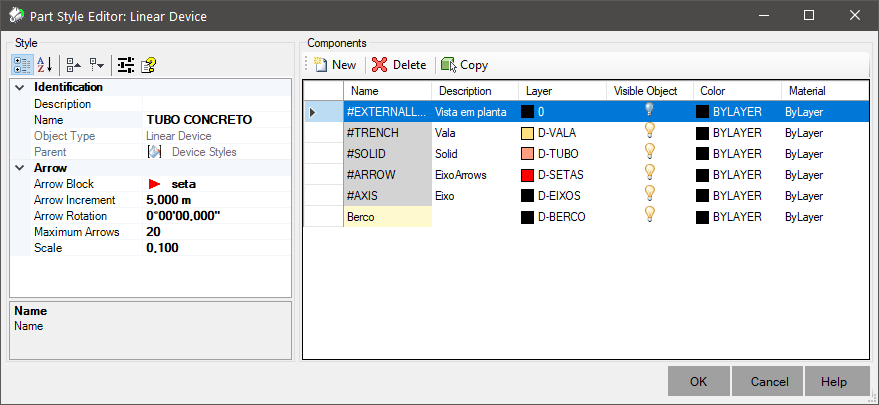
The point device style contains the following basic components, which appear in the Components frame:
- Solid -
settings for drawing the device solid, when no specific component (cover, body, chimney, floor, etc) is specified
- Ditch - settings for drawing the solid of the excavated trench
- Plan View - settings for projecting the plan view.
Note: the plan view is generated from a point above the device, so only the outer contours will be visible
- Directional Arrows - blocks drawn on the device axis in plan view
- Axis - view of device axis in plan view
- Hatch - plan view of the device's hatching.
It is necessary to include the flow that calculates the hatching boundaries within the device modeler
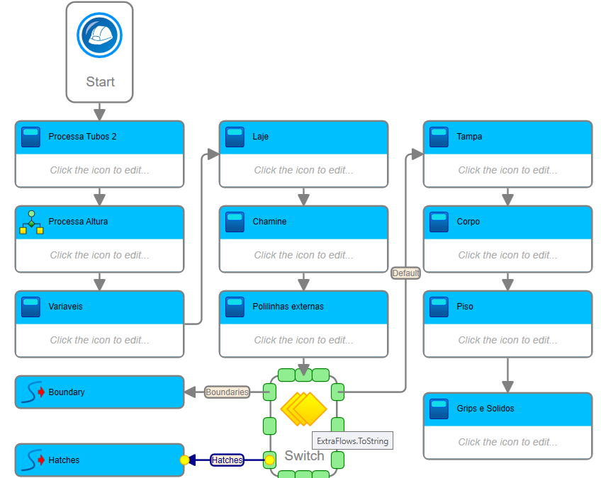
- Slope Pattern - the transverse lines drawn to represent the slope of the excavated trench
- Trench - the 3D solid of the trench excavated to construct the device.
You must enable the excavation calculation mechanism under Standards / Excavation and configure the device to calculate the excavation
In the Components frame, configure the columns for each device component:
- Name (Name, String) - component name
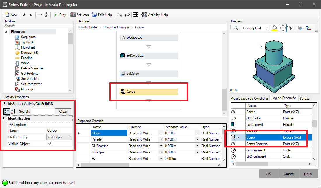
Note, for devices containing more than one solid, for example: a manhole, with cover, chimney, slab, body and floor, all with different materials:
This name must match those device component names, which appear in the builder of the device and which are exposed by the activity  Expose Solid:
- Layer - layer on which the component should be drawn in the model space
- Visible Object - indicates whether the component should be drawn or not
Note: this is different from turning the layer on/off.
The component will or will not be part of the device definition
- Color - color in which the component will be drawn
- Material - material to be applied to the component when it is rendered
- Description (Description, String) - description associated with the component
Use to give context
To edit the color, line style, etc, click the right mouse button on the cell and to rename the layer, click the cell's name and
edit your content.
Observe the norms for naming AutoCAD layers, avoiding the use of invalid characters.