Extra processing flows - Contour extraction
The SOLIDOS modeler can be used to model one or more external contours that will be used to cut out a surface, producing this effect:
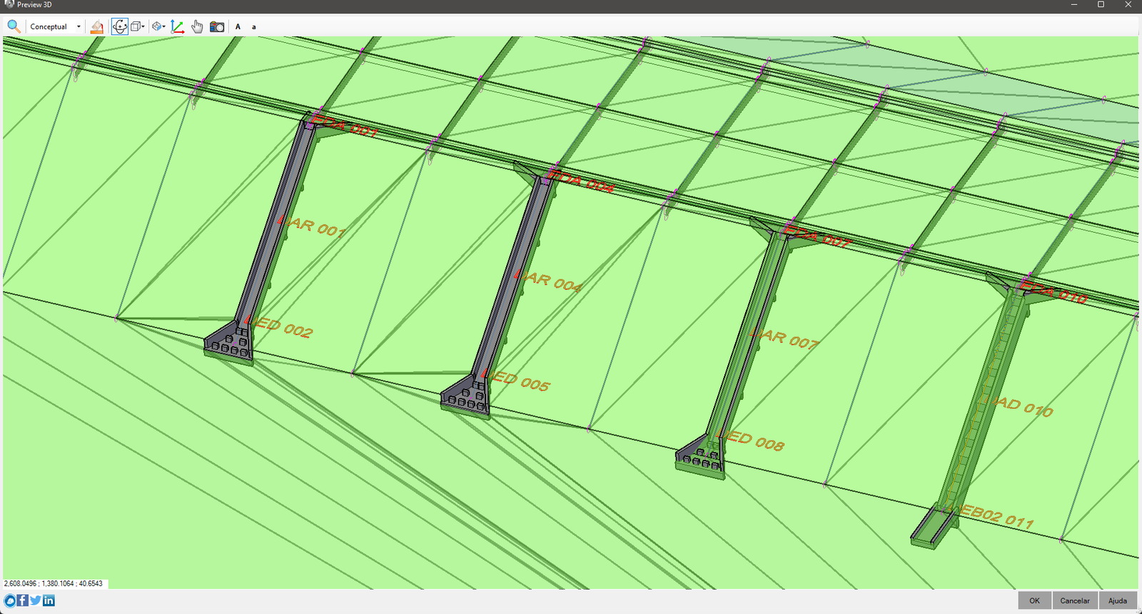
Note the waterfalls on the left. They are not hidden by the surface (created with the command
 SEXTRACTBOUNDARIES
). p>
To use this extra flow, follow the steps:
- Choose a point in the flowchart to stop and insert an
 IF
IF
Tip: choose a point where you already have all the information needed to create the external contour, even if you don't model the device itself
- Create a flowchart to draw an external contour. The most "difficult" ones are for those longitudinal devices:
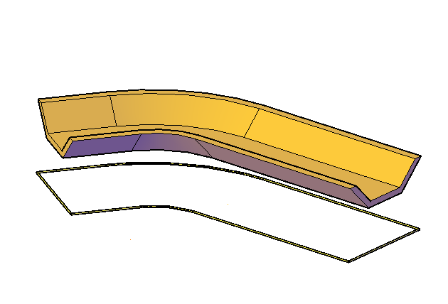
- An example of a point device:
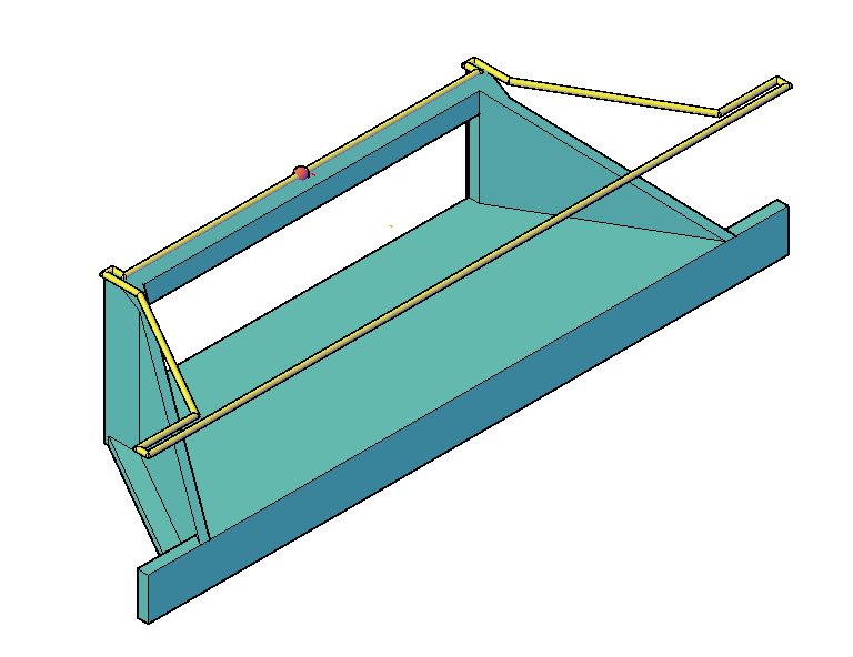 Note that in this device, the contour will be the external projection of the walls, so I chose a point on the flowchart where I already have the points calculated:
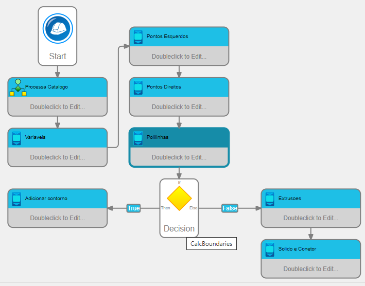
Important notes:
- The flowchart that performs the extraction of the external contour is only called by the command
 SEXTRACTBOUNDARIES
- Any changes to the device properties while executing the SEXTRACTBOUNDARIES command will be ignored
- Any solids or blocks exposed during execution of the SEXTRACTBOUNDARIES command will be ignored
- If you want the contour to be visible in Model Space, you must create a flowchart that exposes this contour, in the same way you do to expose the device's solids:
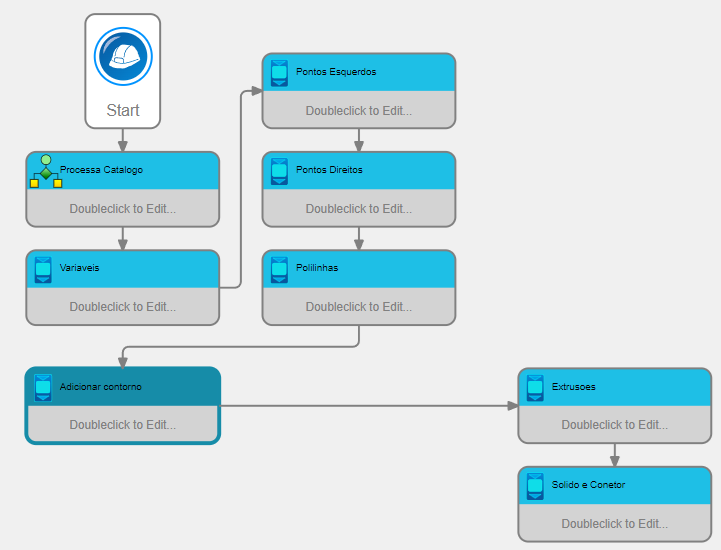
Compare this flowchart with the previous one. It does not check whether the flow is to calculate the contour or to model the solids.
- The process of modeling external contours can be time-consuming for complex contours, so avoid the situation above, always preferring to separate the device construction flows while creating the external contour


![]() SEXTRACTBOUNDARIES
). p>
SEXTRACTBOUNDARIES
). p>


