 SEXTRACTBOUNDARIES
The command
 SEXTRACTBOUNDARIES extracts the outline of the selected devices and adds it as a boundary HIDE on the selected surface
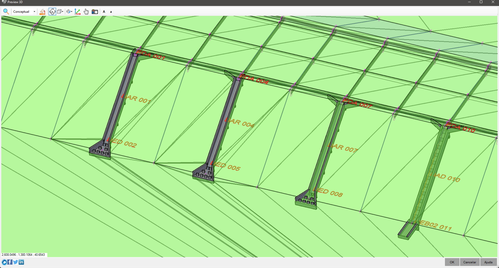
It will be useful when you want to cut the surface to show the device, producing this effect:

Note that the water falls on the left are not hidden by the surface
Before starting, check if the device provides an external contour:
- Open the device modeler
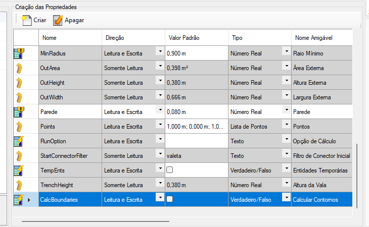
- Note the Property Creation Frame
In it, locate the CalcBoundaries property:

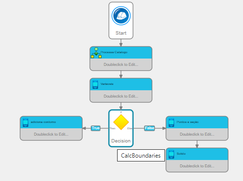
- Observe the modeler flowchart:

If it uses this variable, then it models an external contour
(in the catalogue, look for Valeta de Proteção de Concreto (DNIT V2))
- To create an external contour, use the
 Expose Curve tool:

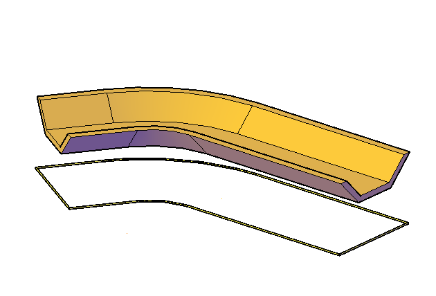
Note, not every device requires an external surround. Buried boxes, for example, do not cut the surface. In the example above, to create this outline, I followed these steps:
- Get the axis of the device projected on the XY plane
- Make an offset from this to the left side
- Make an offset like this to the right side
- Reverse the direction of the curve resulting from the right side
- Create line from the beginning of the left curve to the end of the right curve
- Create line from the end of the left curve to the beginning of the right curve
- Join the curves, forming a closed perimeter
- Expose this perimeter with
 Expose Curve
It becomes easier to understand when you open the modeler and check the flowchart
To use, call SEXTRACTBOUNDARIES from the command line, menu, toolbar or Ribbon
- It will be prompted to select the devices from which you want to extract the contour
- Select the surface that will be painted. receive the Boundaries to type HIDE
 Note:
Note:
The surface will be smooth. If you receive boundaries that modify the triangulation, then avoid modifying work surfaces.
Create a copy of the reference surface and use it
- On the screen that opens, enter the parameters:
- Object
- Boundary Template - name template to use in the name of the boundary added to the database. surface
- Overwrite - if already there is a boundary with the name (calculated in the boundary template) specified, overwrite
- Component Name - name of the component to extract from devices
- Tolerance
- Tolerance - Tolerance when considering nearby points
When calculating the points, overlaps or collinear points may occur.
These can be suppressed, since they will not change the area of the polygon and it is also a preventive measure against the "IllegalBoundary" error, which occurs in these cases
- Arcs, polyline arcs and open ellipses
- Maximum Arc Division - maximum number of divisions of arc segments
- Minimum Arc Division - minimum number of arc segment divisions
- Arco Subdivision - distance and between the points of the arc subdivision
- Closed circles and ellipses
- Maximum Circle Division - maximum number of circle divisions
- Minimum Circle Division - minimum number of circle divisions
- Subdivision of the Circle - distance between the points of the subdivision of the circle
- Splines
- Maximum Spline Division - maximum number of spline divisions
- Minimum Spline Division - minimum number of spline divisions
- Spline Subdivision - distance between spline subdivision points
- Click OK, the surface will be rebuilt
Note that this curve is not normally represented in Model Space, as the flowchart only generates this curve when the SEXTRACTBOUNDARIES command is called. Also note that in the flowchart, any changes to the device will be ignored when running the flowchart that exposes the outer contour
 Note: To be able to use this command, a
license is necessary.
![]() SEXTRACTBOUNDARIES extracts the outline of the selected devices and adds it as a boundary HIDE on the selected surface
SEXTRACTBOUNDARIES extracts the outline of the selected devices and adds it as a boundary HIDE on the selected surface


![]() Note: To be able to use this command, a
license is necessary.
Note: To be able to use this command, a
license is necessary.