Creating
Some rules for the release of sewage and drainage systems:
-
Draw pipes from upstream to downstream, that is, the direction of flow
-
A structure can only have a pipe coming out
-
A structure can have any number of pipes going from its geometry which allow
-
All pipes must have a start structure and a downstream structure even a null
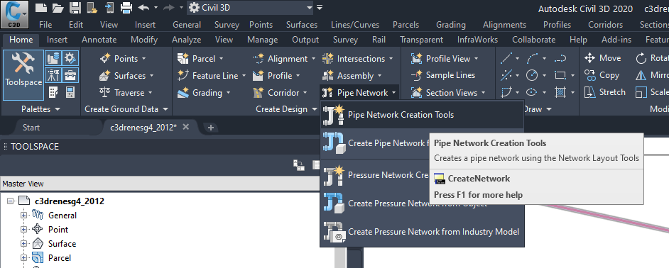
Understood these rules, use the command CreateNetwork:
-
"Network Parts List" choose Parts List "DRAIN"
 If you do not have a Parts List with this name,
see how to create the topic Parts List
If you do not have a Parts List with this name,
see how to create the topic Parts List
-
"Surface Name" set as the final paving surface
-
"Alignment Name", you can leave it blank, as we draw networks in various parts of the allotment
-
"Structure Label Style" and "Pipe Label Style" leave blank texts only hinder during launch
Like this:
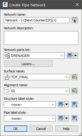
It will open a small bar tools, see:

In toolbar, see the footer.
We have the surface, the "Parts List" and alignment set.
Launch the network can happen in places where there were modeled roads and in these cases
we need to use the natural terrain as a reference elevation.
If this happens, click the icon  surfaces on the bar and choose the natural terrain.
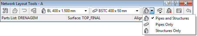
Choose the structure and pipe, as shown:
See that has a button that you set up are drawing pipes and structures (default option), or just pipes or structures:
Civil 3D is now asking the insertion point.
Click the insertion point of the structure amount.
Then click the other points.
If you need to change the structure, choose from the list of toolbars.
Likewise, it can choose another pipe.
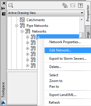
If the toolbar disappear, locate it in the Toolspace/Prospector/Pipenetwork, click the
Right click on it and choose "Edit Network"
When you need to connect a pipe to a structure, Note: that a circle appears next to the structure:
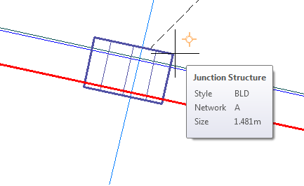
It tells: find a structure here, I attach the pipe in it?
Then you have two options: click INSIDE structure or OUTSIDE.
If you click inside the pipe will be connected to the existing structure, if you click outside
will be designed a new structure and this has nothing to do with the existing one.
When you need a pipe split into two parts, select the toolbar option to draw
only structures and approach the mouse pipe to be divided.
Should appear one Osnap with two squares:
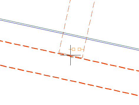
It reports that found that position the pipe, and if you click there, the pipe will be divided and
structure will be inserted at that position.
This applies only to DRAIN
networks:
After launching the culverts, can already draw the contribution areas, with CLOSED
polylines. Then use the command  CAREA
to associate this polylines with culverts.
CAREA
to associate this polylines with culverts.