 Extra processing flows - Device hatching Extra processing flows - Device hatching
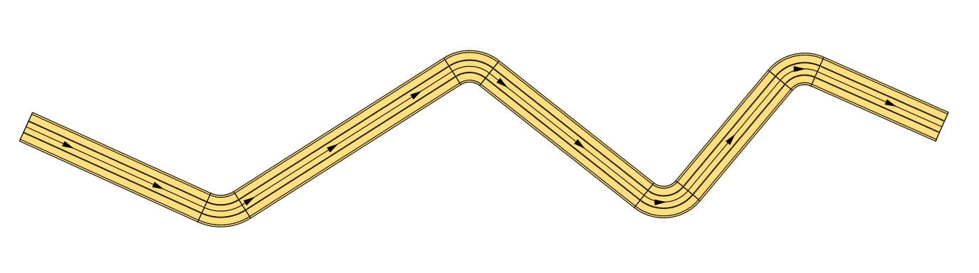
When creating a plan view presentation drawing, it is common to represent a hatch pattern beneath the device, alongside directional arrows, the centerline, or the plan projection. In SOLIDOS, to draw such a hatch, you must define one or more closed polygons to serve as boundaries for the device's hatch pattern—for example:
Since each device has a unique geometry, the person modeling the device must determine what the boundary geometry will look like. Therefore, the modeler includes a specific workflow for this purpose:
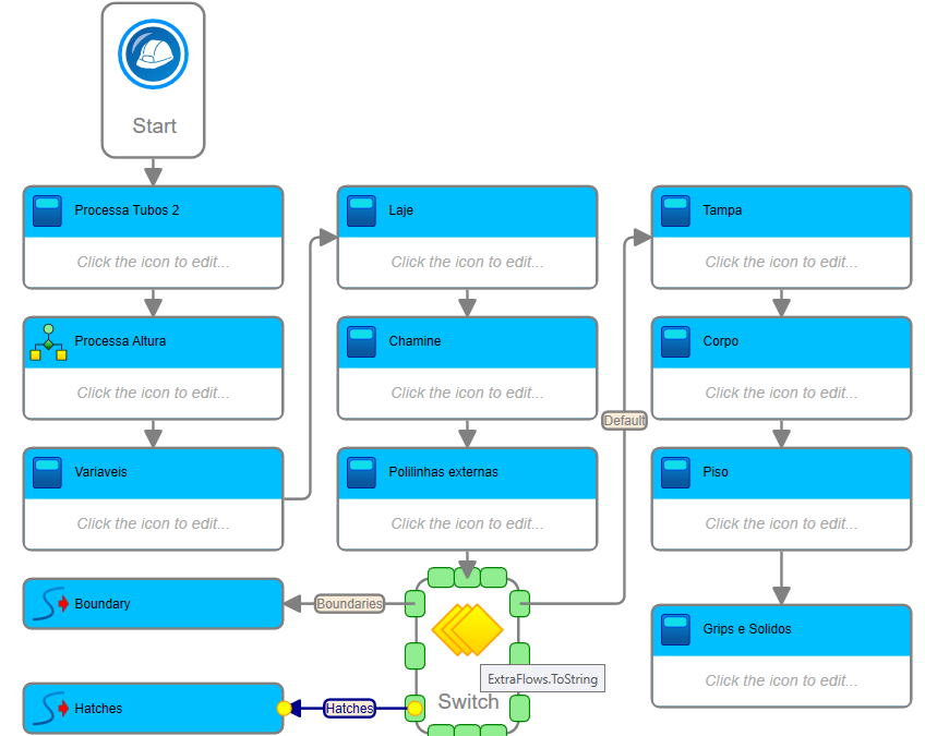
Note that in this case, the boundary generated for use with the  SEXTRACTBOUNDARIES command coincides with the boundary required for the hatch pattern. We can therefore reuse it—as shown in the image—by setting the following condition in the workflow:
Here, CalcBoundaries indicates that the workflow will be used to calculate the clipping boundary for the selected surface, while CalcHatches directs the workflow to calculate the hatch boundary.
Note that these do not have to be identical, nor is it necessary to calculate both.
For instance, in the case of pipes, they are buried underground. This means that they are not visible from above on the natural ground and therefore do not need to cut the surface using the SEXTRACTBOUNDARIES command.