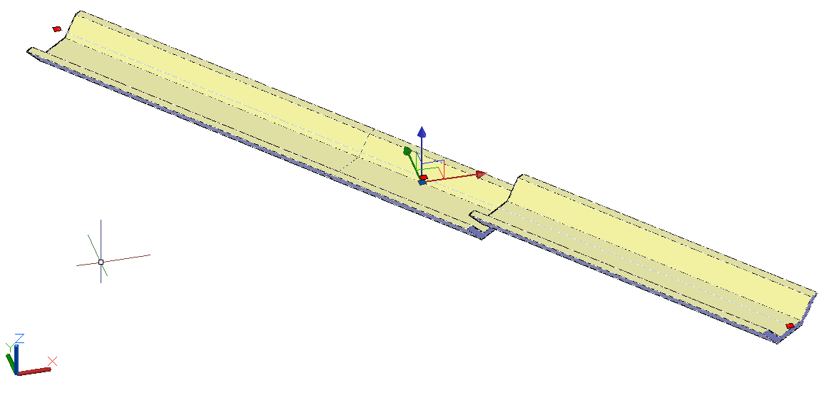
Some longitudinal devices present deformations after launch, for example:

This problem can have 2 causes:
In the event of hardware failures
The fact that the vast majority of projects are "georeferenced" by matching AutoCAD coordinates to UTM, cause the program to lose precision when representing real numbers, since the integer part of the number uses many bytes leaving few for the fractional part (E=651647.547, N=7845327.697, for example). This loss of precision causes hardware failures, which results in situations like this:
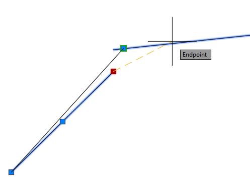
In this image, the rightmost line is an ARC. Note that visually, the ENDPOINT does not coincide with the end of the line.
This issue is related to hardware acceleration and use of large numbers. When the acceleration is turned off, the problem does not appear. To test this bug:
To fix this problem, update your video card drivers, make sure it is an Autodesk-approved card, or turn off hardware acceleration using the 3DCONFIG (GRAPHICSCONFIG) command and do a REGENALL
In case of errors in the modeler
Longitudinal devices are typically created using the
![]() Sweep tool.
This tool has properties that directly influence how the device will be modeled.
One of them concerns the "verticality" of the section to be modeled.
Sweep tool.
This tool has properties that directly influence how the device will be modeled.
One of them concerns the "verticality" of the section to be modeled.
In Civil 3D, Corridors are modeled using Assemblies that are always vertical. Therefore, when viewed from above, we do not see the "shapes" of the selected section, only the links:
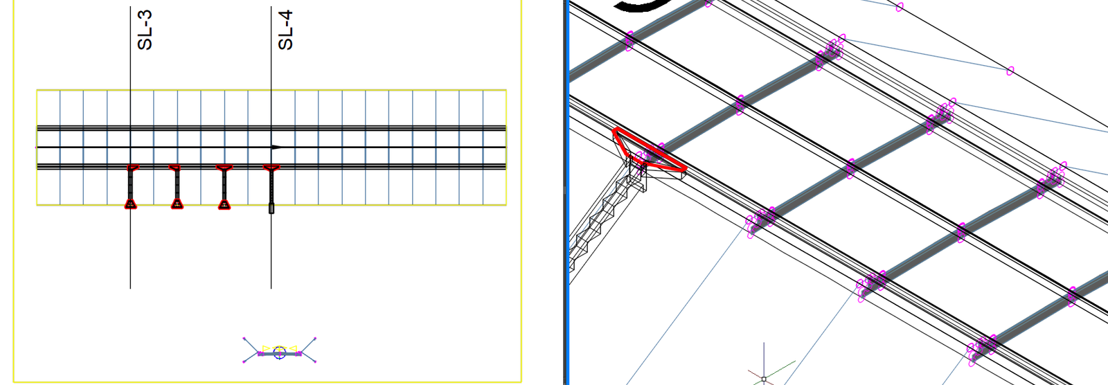
Look at the left window. In it we see the corridor from above and therefore you cannot see the hatches of the templated section, which are visible in the frame on the right, as it is in 3D.
In SOLIDOS, the tool
![]() Sweep, can model as if it were a corridor or varying the section to better represent the element:
Sweep, can model as if it were a corridor or varying the section to better represent the element:
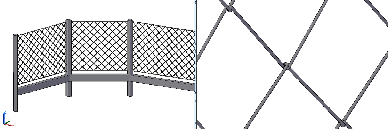
Note the "wire" of the chain link fence (available in the catalogue). To model this wire, the section needs to be modeled on the axis, always changing direction.
Now, in the context of a longitudinal device, modeling the non-vertical section is a bad idea, as the section does not start/end vertically if the slope of that device is not zero.
If you are using an old version of the plugin, you may have this non-vertical section issue. For example, the trapezoidal channel:
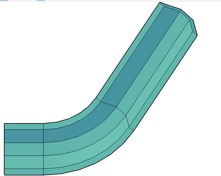
Note the deformed section at the top. For coordinates close to the origin, it works normally. But in "georeferenced" projects errors may occur.
The modeler in this section is not vertical. Open this modeler, go to Start / Solido. Let's see how it was created:
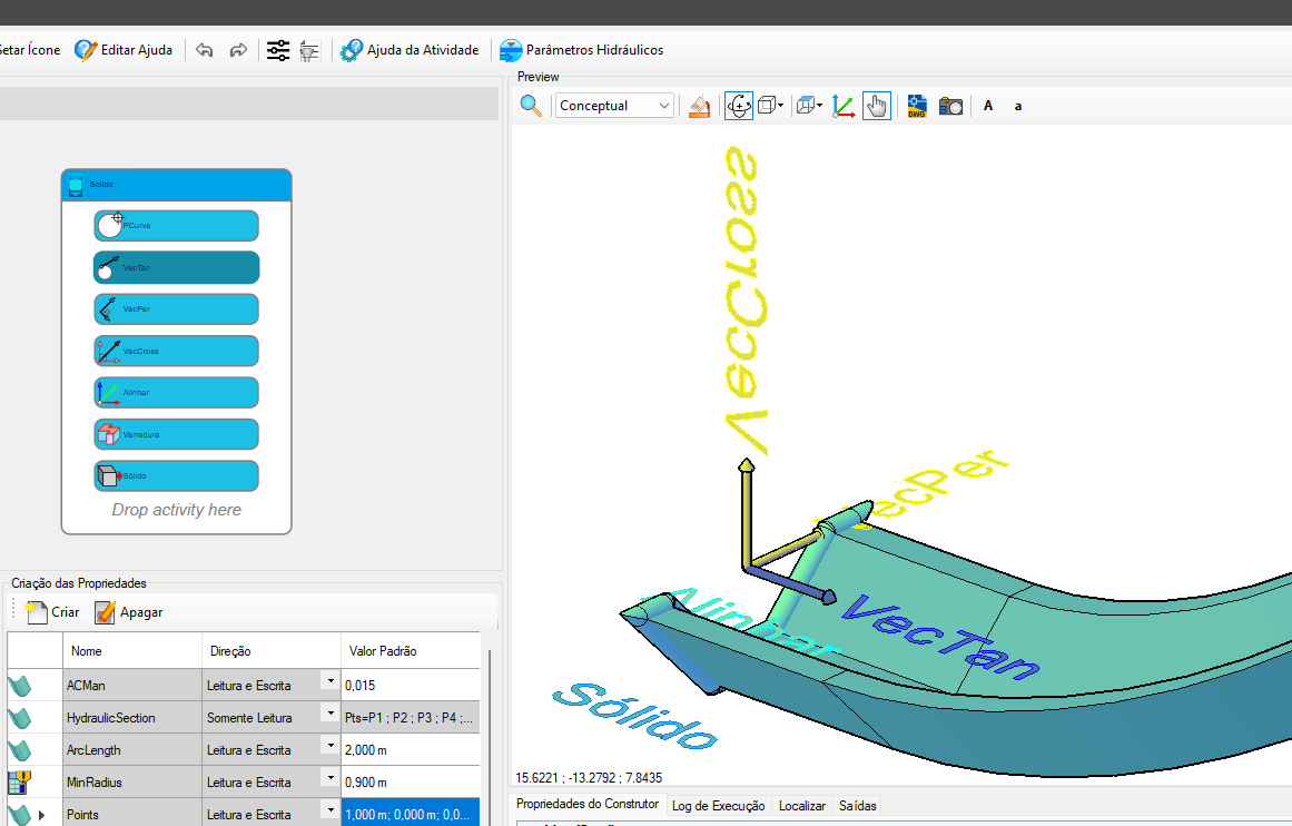
To make this section vertical, follow these steps:
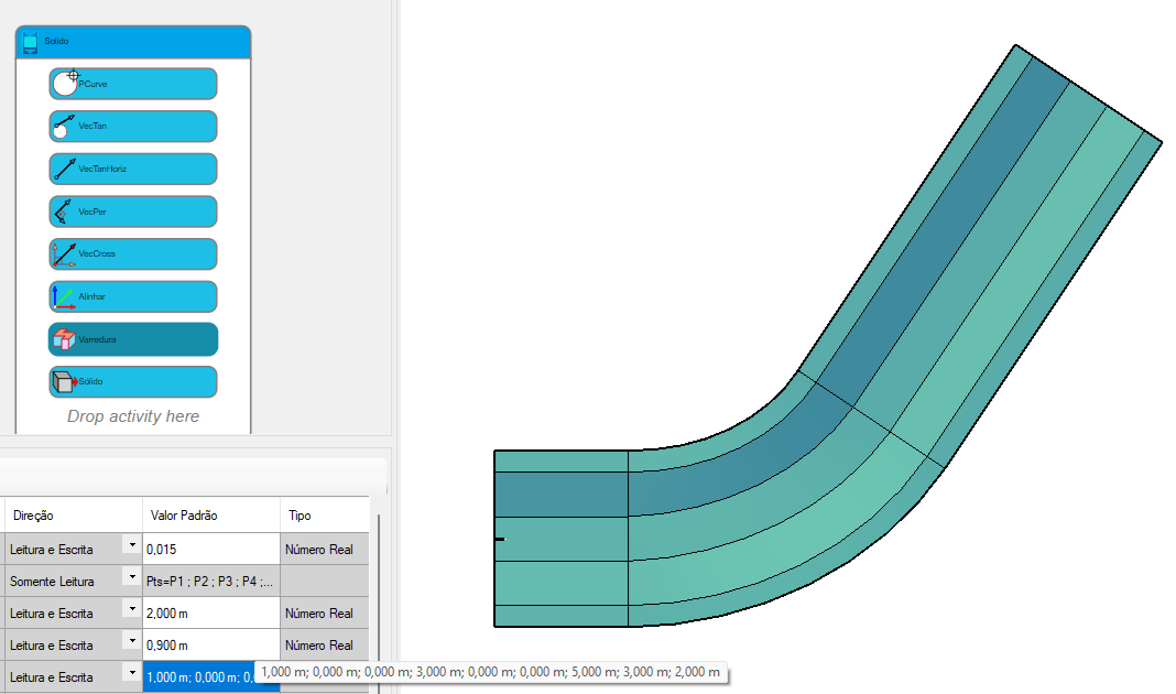
Obviously, some devices may vary the names above, however the concept is the same. If you created models using the
![]() Sweep tool and observed the error described here, correct using the steps described here.
Sweep tool and observed the error described here, correct using the steps described here.
Note that in the case of the fence, we must use the sweep section with the option Vertical Section = False, so that it does not deform along the axis.
The devices in the current catalog are all already corrected.