Culverts Design - Circular nº 5 of the "Bureau of Public Roads"
Dimensioning of culvert according to Circular nº 5 of the "Bureau of Public Roads"
Engineering seeks the best work at the lowest cost. Based on this premise, in the case of culverts, there is no inconvenience in damming or increasing the depth of the watercourse upstream of the work, if this is technically feasible, in all its aspects (functional, safety, economic and environmental)
- Initial Data
- Q - Project flow
- L - Culvert length
- HWadm - Water height admissible upstream
- n - Manning coefficient
- I - Culvert slope
- A - Culvert cross section area
- Critical Section - Values for dc, Qc, Vc, Ic, and dc will be required for the critical flow (see flow in the critical flow)
- dc - critical tie
- Qc - flow in the critical flow condition (Fr = 1)
- Vc - flow velocity in the critical flow condition (Fr = 1)
- Ic - culvert slope for critical flow condition (Fr = 1)
- Identification of variables - for dimensioning, assuming input or output control:
- Suppose input control
Inlet control means that the discharge capacity of the culvert is controlled at its entrance by the depth of the water upstream (HW), by the geometry of the inlet mouth and the cross section of the conduit
In this condition:
- Hc = dc + Vc ^ 2 / (2 * g)
- K, M, Ks, Y, c, depends on the type of the culvert
- LimInf, LimSup, Ku depend on the system of measurement units:
- International System (SI, metric)
- LimInf = 1.93
- LimSup = 2.21
- Ku = 1.811
- Imperial System (feets)
- LimInf = 3.5
- LimSup = 4.0
- Ku = 1.0
- QAD = Q / (A * D ^ 0.5)
- Inlet Condition
- Not submerged, if QAD ≤ LimInf
- Submerged, if QAD ≥ LimSup
- Transition, if LimInf < QAD < LimSup
- HWDinlet, depends on the condition of the inlet:
- Not submerged
- Eq - form of the equation, can be:
- Eq = 1: HWDinlet = Hc / D + K * (Ku * Q / (A * D ^ 0.5)) ^ M + Ks * I
- Eq = 2: HWDinlet = K * (Ku * Q / (A * D ^ 0.5)) ^ M
- Submerged
- HWDinlet = c * (Ku * Q / (A * D ^ 0.5)) ^ M + c + Ks * I
- Transition
Interpolate QAD on the line (LimInf,hwdInf) to (LimSup,hwdSup):
- qEscInf = LimInf * A * D ^ 0.5
- qEscSup = LimSup * A * D ^ 0.5
- hwdInf = função(não submerso, qEscInf)
- hwdSup = função(submerso, qEscSup)
- HWDinlet = (QAD - LimInf) * (hwdSup - hwdInf) / (LimSup - LimInf)
Where:
- Hc - specific height at critical depth
- K, M, Ks, Y, c depends on the type of culvert (see Inlet Coefficients)
- Ku - unit conversion
- LimInf - lower limit of the ratio (QAD = Q / (A * D ^ 0.5)) of the non-submerged flow with inlet control
- LimSup - upper limit of the ratio (QAD = Q / (A * D ^ 0.5)) of the submerged flow with outlet control
- Eq - form of the equation for calculating the HW/D ratio for inlet control (HWDinlet)
- HWDinlet - relation HW/D for inlet control
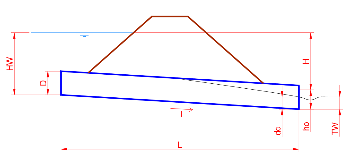
- Suppose Outlet Control
drainage of drains with outlet control can occur with the flue totally or partially filled, in part or in its entire length.
Consider:
- ho = se ( TW >= D ; TW ; ( dc + D ) / 2 )
- Ke = depends on the culvert type, see Outlet Coefficients
- H = (1 + Ke + (2 * g * n ^ 2 * L ) / ( Rh ^ (4 / 3) ) ) * V ^ 2 / ( 2 * g )
- HWDoutlet = H + ho - I * L
Where:
- TW - height of the water flowing into the stream, downstream of the culvert
- ho - equivalent piezometric height
- Ke - Head Loss coefficient when entering structures
- H - head loss at the entrance
- HWDoutlet - HW/D ratio with outlet control
- Adopt the Biggest HWD
- Control Type = IF ( HWDinlet > HWDoutlet ; inlet ; outlet )
- HWD = Maximum (HWDinlet, HWDoutlet)
- HW = HWD * D
- V = depends on the culvert control type:
- Outlet:
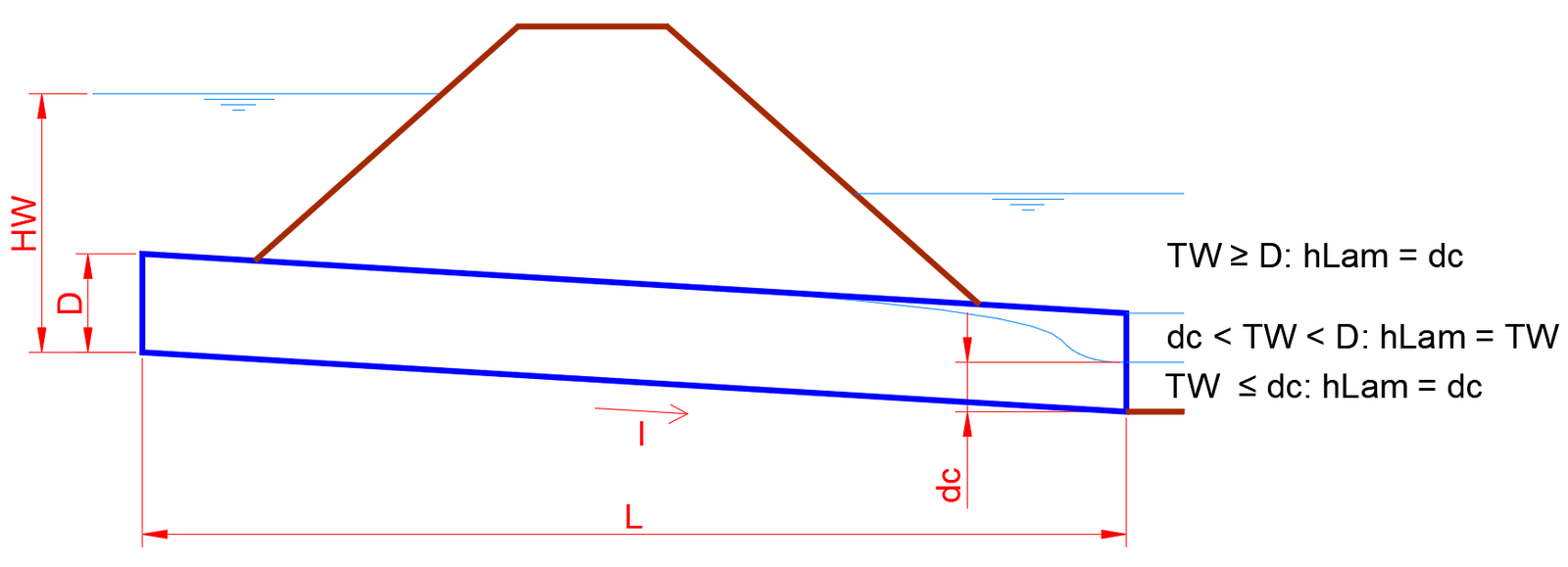
- hLam = function(TW, dc, D)
- TW = D: hLam = D
- dc < TW < D: hLam = TW
- TW ≤ D: hLam = dc
- Rh = Am / Pm
- V = Rh ^ (2 / 3) * I ^ 0.5 / n
Where:
- hLam - height of the flow sheet at the end of the culvert
- Am - wet area for hLam
- Pm - wet perimeter for hLam
- Rh - hydraulic radius
- V - Speed at the exit of the culvert
- Inlet
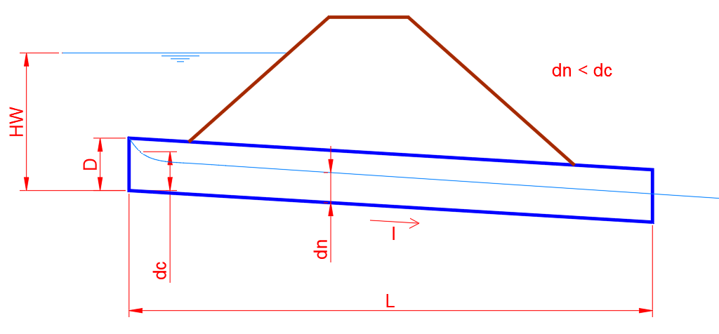
It works as a channel, so:
- arbitrate hLam until Qcalc = Q
- V = Rh ^ (2 / 3) * I ^ 0.5 / n
- Qcalc = Am * V
Where:
- hLam - height of the arbitrated flow sheet
- Am - wet area for hLam runoff
- Pm - wet perimeter for hLam flow height
- Qcalc - flow calculated for hLam height
- V - flow velocity at the end of the culvert
- Q - project flow
The HY-8 uses flow type numbers (table below) to help define how manhole flow is calculated.
Flow type numbers are based on USGS flow type numbers 1 through 6 (USGS 1968) supplemented with:
- Simplification of HW = D to indicate submergence at the inlet,
- Flow type 7 for outlet control with M1 or M2 profile (coming soon to SOLIDOS) for most manhole with HW> D
- Standard water surface profile indicators (S1, S2, M1, M2, H2 and H3, coming soon to SOLIDOS) and
- Residual water indicator (n, c, t and f, coming soon to SOLIDOS) for normal, critical, residual and full water
| Table 3.1. HY-8 Flow Type Table |
Type of
Flow |
Type of
Control |
Input
submerged
HW>D |
output
submerged
TW>D |
Extension a
Full Section |
| 1 |
Input |
No |
No |
Nothing |
| 5 |
Input |
Yes |
No |
Nothing |
| 2 |
Output |
No |
No |
Nothing |
| 3 |
Output |
No |
No |
Nothing |
| 4 |
Output |
Yes |
Yes |
Everything |
| 6 |
Output |
Yes |
No |
Most Part |
| 7 |
Output |
Yes |
No |
Partial |
Source: "HYDRAULIC DESIGN OF HIGHWAY CULVERTS", third edition, April 2012
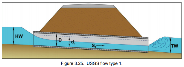
- USGS Flow Type 1 (inlet control) - Figure 3.25 shows flow type 1 with wastewater greater than
critical depth (S1t). For this case, an S1 curve is calculated and used if the S1 curve extends
to the manhole face. If the S1 curve reaches the critical depth, an S2 is calculated and
compared to the S1 curve. If the sequential depth for S2 matches S1 inside the culvert, a JFt code will be displayed and the output speed will be based on residual water. if the sequent
depth is not reached inside the culvert, the jump is assumed to be swept and an S2 is
used to calculate the output speed (S2n). If the residual water is greater than D, the keg flows full into the
At the end, S1f is shown if S1 extends to the input. If S1 reaches the critical point, the JFf code will be
shown to indicate that the S2 curve jumps to full flow in the culvert
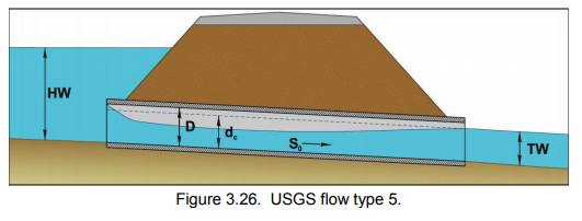
- USGS Flow Type 5 (inlet control) - Figure 3.26 shows flow type 5 with residual water less than
critical depth (S2n). If the Tailwater (TW) is greater than the critical depth, an S1 curve is calculated
and used if the S1 curve extends to the culvert face. If curve S1 reaches the depth critical point, an S2 is calculated and compared to the S1 curve. If the sequential depth for S2 matches S1 inside the culvert, a JFt code will be displayed and the output speed will be based on the tailwater.
If the sequent depth is not reached within the culvert, the jump is assumed to be swept and an S2 is used to calculate the output velocity. If the residual water is greater than D, the
manhole flows full at the end (S1f) is shown if S1 extends to the inlet. If S1 reaches critical, the JFf code will be displayed to indicate that the S2 curve jumps to full flow in the culvert.
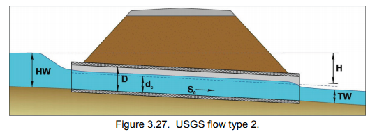
- USGS Flow Type 2 (outlet control) - Figure 3.27 shows flow type 2 with lower residual water than
critical depth. For this case (M2c), an M2 curve is calculated starting at the critical depth at the outlet.
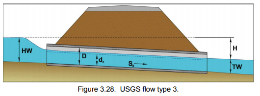
- USGS Flow Type 3 (outlet control) - Figure 3.28 shows flow type 3 with wastewater greater than
critical depth. For this case (M1t), an M1 curve is calculated starting from the depth of the wastewater at the outlet.
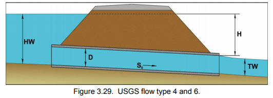
- USGS Flow Type 4 and 6 (outlet control) - Figure 3.29 shows flow type 6 with waste water
depth greater than critical. For this case (FFt), the barrel flows full for most of its length.
An M2 curve is calculated starting at the outlet to determine the length of culvert that will flow completely.
The outlet depth is the residual water for the FFt case and is a critical depth for the FFc case. for flow type
4, the waste water is higher than the manhole crown at the outlet, and the barrel flows full (FFf)
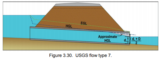
- USGS Flow Type 7 (outlet control) - Figure 3.30 shows flow type 7 with bottom wastewater
critical depth. For this case (M2c), the barrel flows full for part of its length. An M2 curve is
calculated from the output to determine the length of culvert that will flow through. Exit
depth is the wastewater depth for the M2t case and is the critical depth for the M2c case. if the tailwater
is greater than the normal depth (M1t), an M1 profile is calculated
