
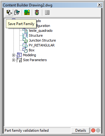
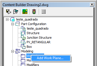
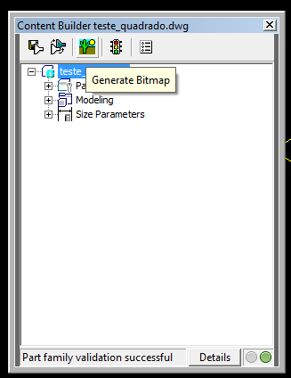
Note that the first node, Part Configuration, must be configured:
- Part Name: TESTE_QUADRADO
- Part Type: Junction Structure, in the case of a manhole or connection box. If it were a wing would be Inlet-Outlet this information sets mandatory variables such as height and background wall and slab thicknesses
- Shape: Box, in this example, the structure is a rectangular box. This information defines some mandatory variables for the model, such as width, height and length.
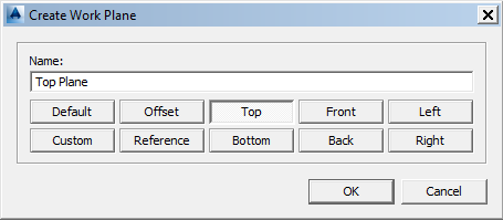
Enter a name, eg Top Plane:
To make it easy to identify on the screen, a square yellow is created in the drawing. It defines the plan we just created.
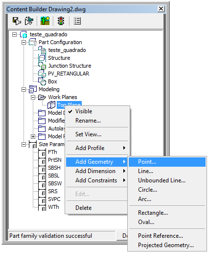
Enter the point in the middle of the yellow square. Use the OSNAP Mid Between two points to facilitate.
The point is created on the screen, color White

Note that after this point will be in color Green. This indicates that it is a fixed geometry.
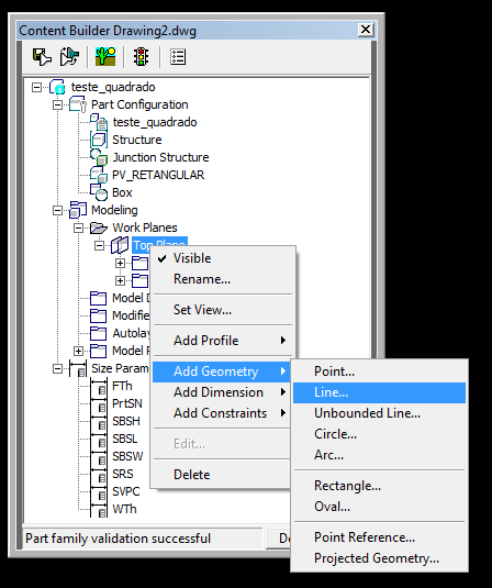


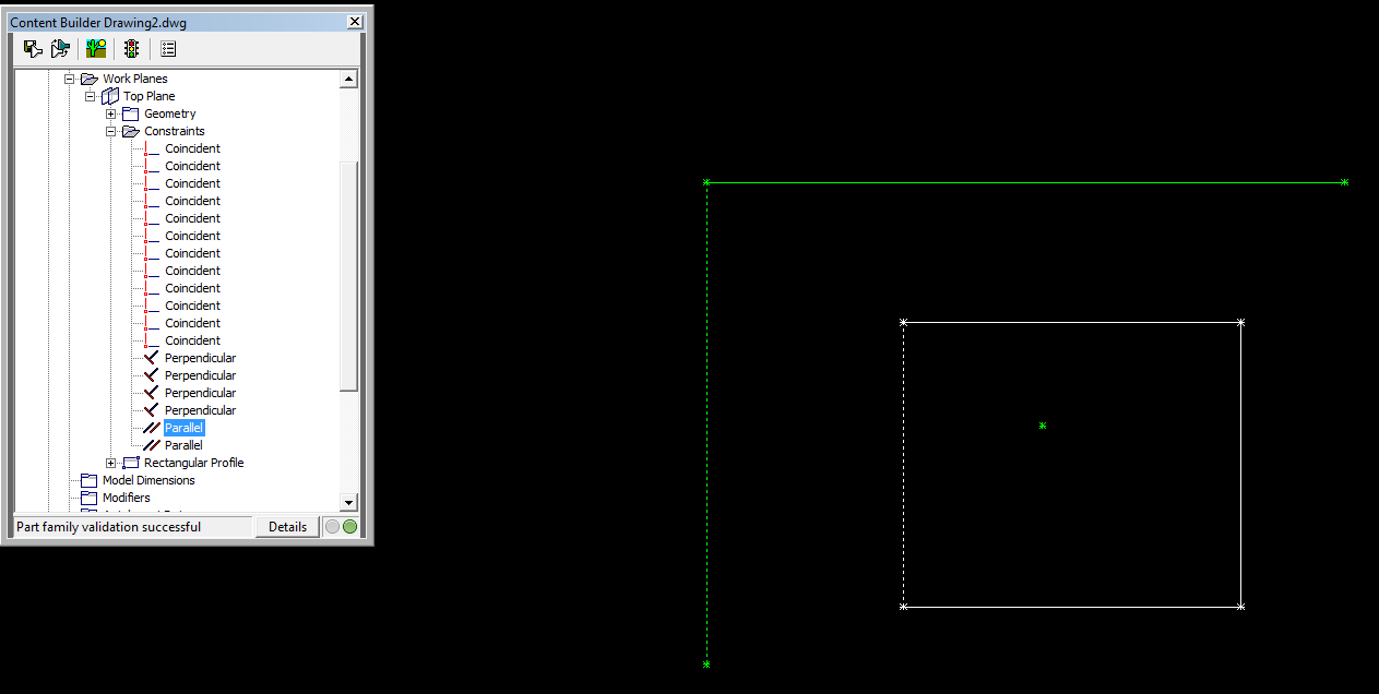
Note that when you select the item on the screen Content Builder, it is highlighted in the drawing screen:

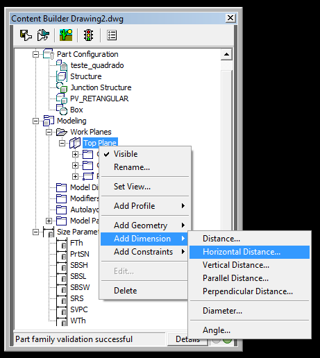
Select two points that define the white rectangle. It is like creating a dimension, so just answer the questions on the command line. Use 150 as a measure.
Note that this measure will only be used to draw something. It will be overwritten later. You can also select the measure on Content Builder:
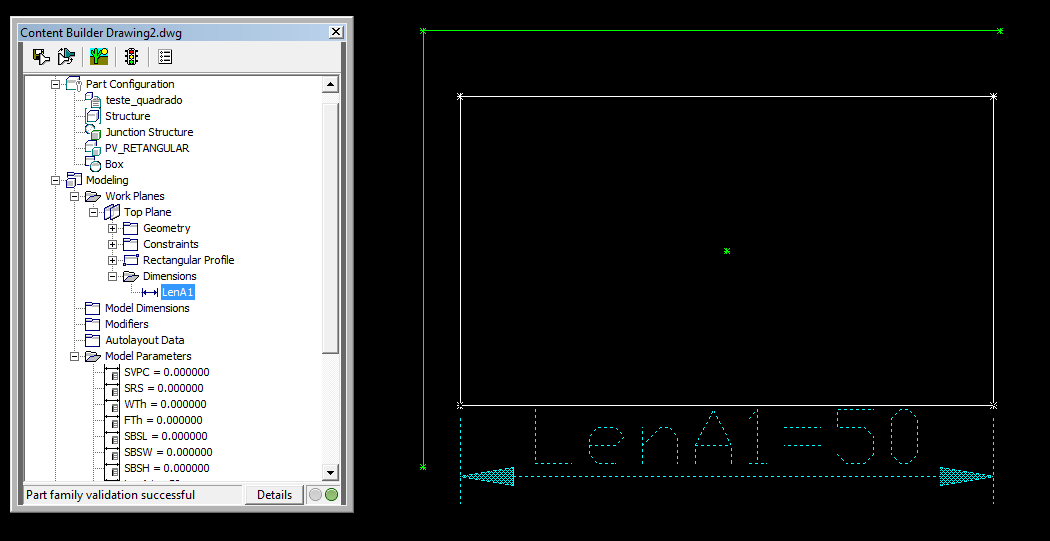
The dimension is called LenA1
Use the value 100. It should look like this:

The dimension is called LenA2

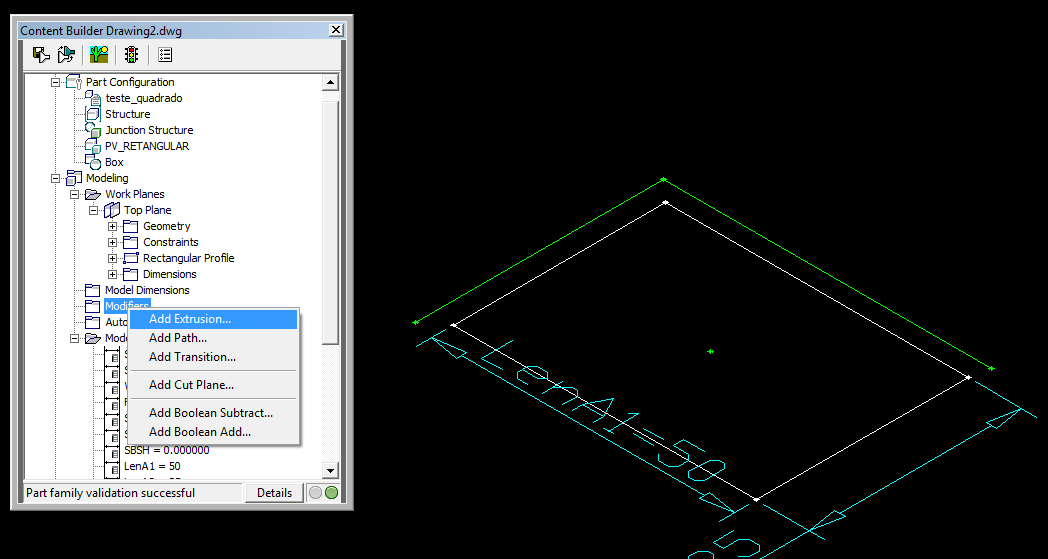
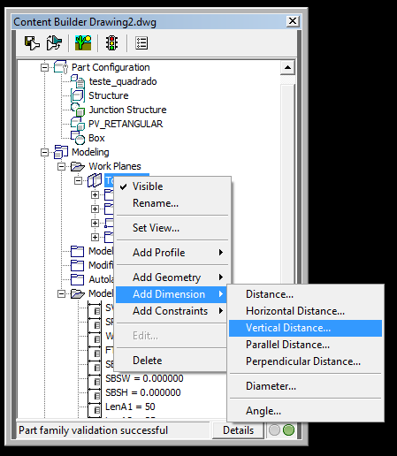
On the screen that opens, set the parameters like these:

This says to extrude down from the "Top Plane" plan, at a distance of 120Ā

Usually the boxes are defined by internal measurements, since the walls can vary depending on the structural design of the box. For the Part Builder understand and manage the size of the structure, you must define the variables that control it. Here is a hint: Despite the Part Builder accept that you create custom variables, practice shows that this does not works as well
| Variable | Name | Description | Note |
|---|---|---|---|
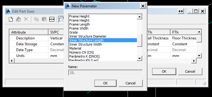
| SIL | Inner Structure Length | Internal length of the structure | Built manually |
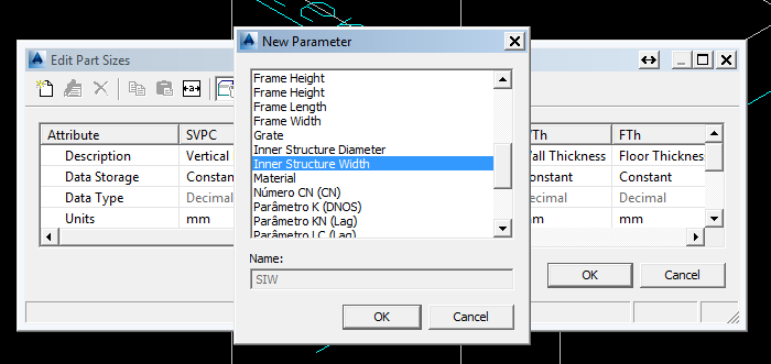
| SIW | Inner Structure Width | Internal width of the structure | Built manually |
| wth | Wall Thickness | Wall thickness | Built to define the type of structure Junction Structure |
| FTH | Floor Thickness | bottom slab thickness | Built to define the type of structure Junction Structure |
| SRS | Rim to Sump Height | box Internal height | This variable is controlled by the blip of the fund dimension profile |
| SBSL | Structure Length | outer length of the box | Built to set the shape and Box |
| SBSH | Structure Height | External Height of the box | Built to set the shape and Box |
| SBSW | Structure Width | External Width box | Built to set the shape and Box |
| PrtSN | Part Size Name | Box Name, size | All structures have |
Note: These variables are defined in a file within the catalog, in Pipes Catalog\AECC Shared Content\AeccPartParamCfg.Xml, see:

Let's not get into this merit yet.
Returning to Civil 3D, we create two variables: SIL and SIW:
Browse and add the variable SIW
We added these two variables, as they are already configured in the Pipes Catalog \ AECC Shared Content \ AeccPartParamCfg.Xml so that you visible to the user in the edit screen:
Later, you will see that many variables are available or not on the screen above.

The program asks you to select the extruded solid. This will create a call dimension LenB1
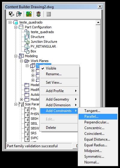
To create the relationships between the variables, click the right mouse button on the node Model Parameters:
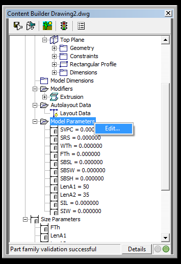
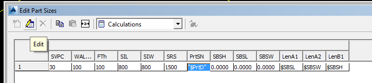
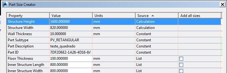
Note the table below. Highlighted the variables that the user can edit later. The others are constants or calculated:

The calculated variables are those that you do not directly control. They are evaluated by mathematical expressions. For example:
- SBSL = 2 * Wth + SIL
- SBSW = 2 * Wth + SIW
- SBSH = SRS + FTH
Reinforcing: Without these three variables, the structures do not appear in the drawing after being inserted
To edit the equation, double-click on the corresponding cell. Interpret the entered equations.
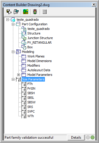
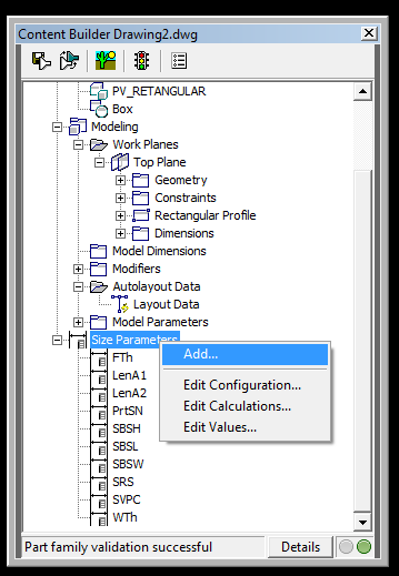
Others, may appear as a number that should be within a range. To set this, click the right mouse button on the node Size Parameters then Edit Configuration:
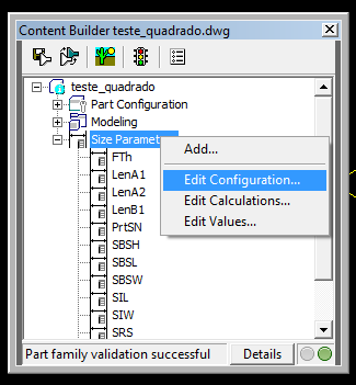
Set up as shown below:

Note: You may not edit the line Data Storage. If this happens, save it, close and reopen:
IMPORTANT: The variables that will appear to the user, need to be with the Visible marked True. Some should not appear. This is the case these: LenA1, LenA2, LenB1. They do not appear on screen Part Size Creator

In this step you can also get this error:
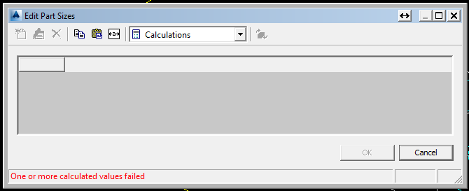
Note that you can not edit values. Again, click to save, close, open again and return to the edit screen
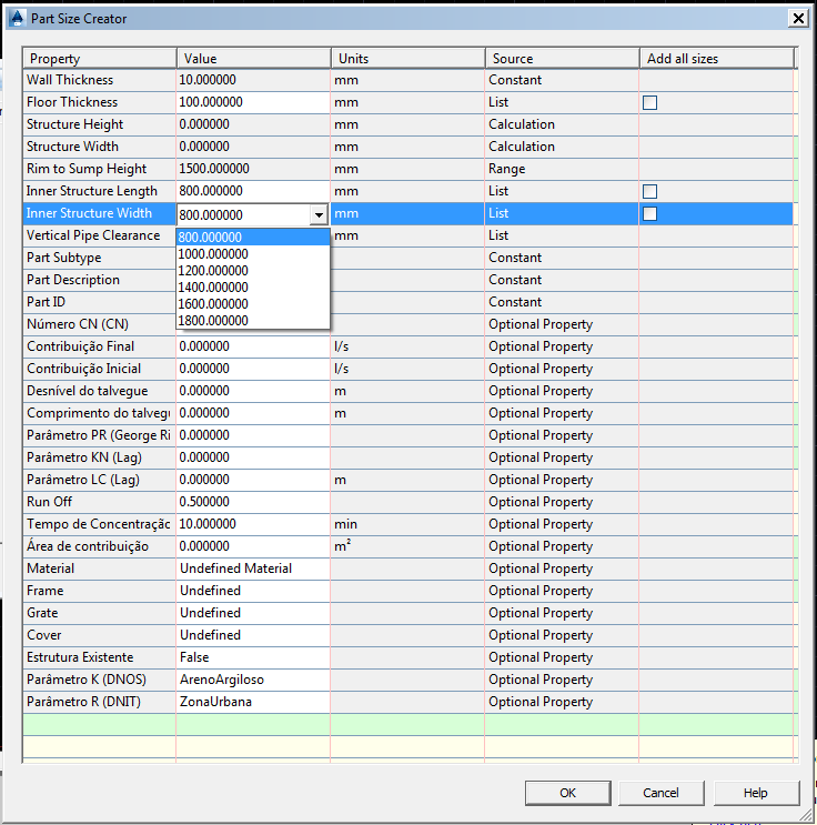
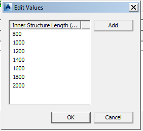
Select the variable SIL for example, and add the values: 800,1000,1200,1400,1600 and 1800, in millimeters:
These are the values available in screen Part Size Creator:
Note that define this variable with units in millimeters on the screen Configuration. So the values need to be in these units. See how it looks:
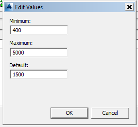
Edit the variable SRS. Note that we define with Data Storage like Range. Because it can take an actual numeric value whatsoever within a range the maximum and minimum also in millimeters:
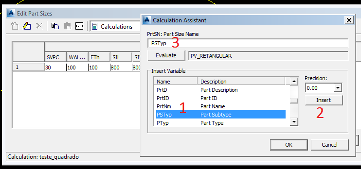
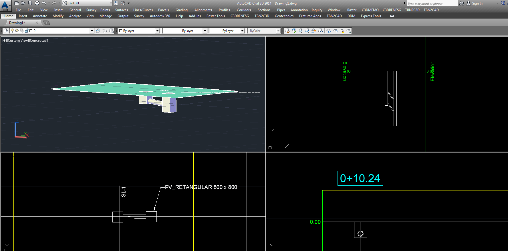
Find the variable SIW, set the Precision to zero and click the Insert. Do the same with SIL. Click the Evaluate button. Should look like PV_RETANGULAR 1000 x 1000
You are free to create this nomenclature. Just watch out for include at least SIL and SIW in order to facilitate the identification of the structure in Parts List.
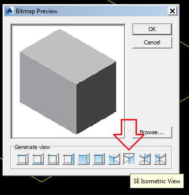
Choose a view:

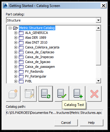
Also, click the Catalog Regen:

When inserting new Part Size, see the available values for SIL and SIW
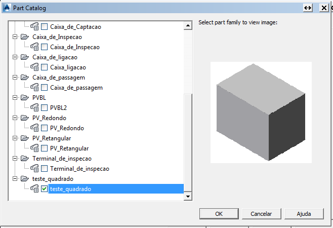
After that, see if the name of the structure was correct:
- Close the Civil 3D
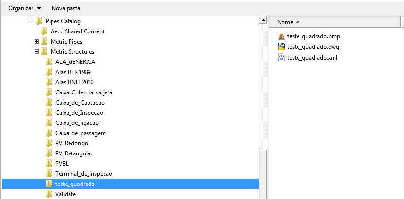
- Navigate to the folder of your catalog, usually in C: \ ProgramData \ Autodesk \ C3D 2015 \ enu \ Pipes Catalog
-
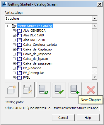
Locate the definition of the structure, which should be in Pipes Catalog \ Metric Structures \ Chapter \, where Chapter is the name
you chose at the beginning of the tutorial:
-
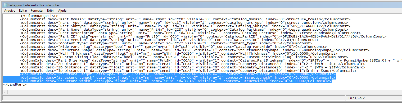
Open the XML file that has the name of its structure with Notepad and go to the end of the file, locate tagged lines:
-
Note that they must have values 0000 to SBSL, SBSW and SBSH, bug partBuilder, as defined equations for this.
Edit to look like this:

Note that only includes equations:- SBSL = 2 * $Wth + $SIL
- SBSW = 2 * $Wth + $ SIW
- SBSH = $SRS + $FTh
- Save the file and close
- Open Civil 3D
- Call the PartBuilder and make the Catalog Regen and Test Catalog Again
-
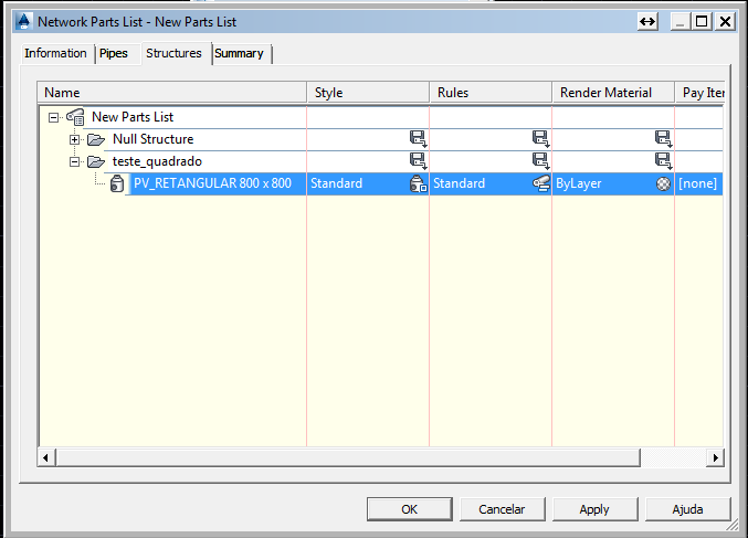
Create a Parts List note that SBSL, SBSW and SBSH now has correct values:
Create pipenetwork and enter its structure: