Macro Editor - Table
You can also insert tables at the memorial.
Tables can be:
-
Static - are tables with number of fixed lines
-
Dynamic - are the tables that can increase the number of lines as needed
To add a table in the memorial click the button  Table.
Let's do an example:
Table.
Let's do an example:
-
Call the
 LegalDescriptionCreator or TableCreator command
-
Add a macro to insert the polygon list in the subdivision: [Poligonos(O0|R1|S1|Q7|I1)], like this:

-
Click the text [Poligonos(O0|R1|S1|Q7|I1)] and click
 Edit
Edit
-
Click Add Table button:

-
Add 3 rows clicking
 Add row button
-
Add 6 columns by clicking the button
 Add Column
-
Click mouse left button in to upper left cell, keep pressed, and go to the upper right cell, and click
 Merge button
-
Fill cells:
| [Nome(C1)]
|
|
Start Vertex
|
End Vertex
|
X
|
Y
|
Length
|
Azimuth
|
|
|
|
|
|
|
|
-
Click bottom left cell and choose Segments property in properties list.
The table in this example is the dynamic type, for each vertex of the polygon will make the table increase in a row.
But see, the properties that will write
in the table refer to each edge of the polygon, so we will click the
 Expand button:
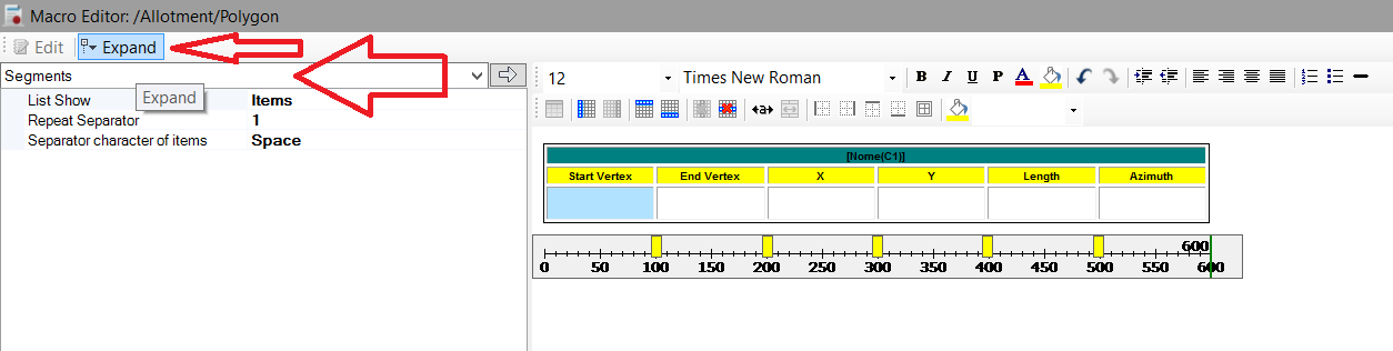
Note that this button is only available if the cursor is in a table cell and a property of type List is selected
-
After clicking the Expand button, note that the properties box shows segment of property and the title bar changes.
Thus for each column will be possible to add suitable properties:
ĀĀĀĀ
|
[Nome(C1)]
|
|
Start Vertex
|
End Vertex
|
X
|
Y
|
Length
|
Azimuth
|
|
[VerticeInicial(I1)]
|
[VerticeFinal(I2)]
|
[VerticeInicial(I3)]
|
[VerticeInicial(I4)]
|
[Comprimento(R0|D3|P3|Um|T2|M2|N0)]
|
[InfoAngulo(G1|Ugrau|A1|E1|R0|D3|P3|M2|N0)]
|
-
Note that will only work if the cell has its line associated with the correct path, ie, [VerticeInicial(I1)] will show the
initial vertex of the segment only if the title bar show the path Allotment/Polygon/Segments/Segment:

-
Click the text [VerticeInicial(I1)], and click Edit button
-
Add the Name property ([Nome(C1)]):
Ā

-
Click OK button
-
Repeat for other columns, but, choosing another properties:
-
Column Start Vertex, add the name ([Nome(C1)])
-
Column End Vertex, add the name ([Nome(C1)])
-
Column X, add the X of location ([Coordenada(S0|Um|R0|D3|P3|T2|M2|N0)])
-
Column Y, add the Y of location ([Coordenada(S1|Um|R0|D3|P3|T2|M2|N0)])
-
Column Length, add the length of the segment ([Comprimento(R0|D3|P3|Um|T2|M2|N0)])
-
Column Azimuth, add the azimuth of the segment ([InfoAngulo(G1|Ugrau|A1|E1|R0|D3|P3|M2|N0)])
-
Click OK button, to return to Table Creator screen
-
Click the button
 Save to save the current template:
Ā
Save to save the current template:
Ā

-
Click OK button to process
-
The result of the example should be:

The example set is available in the program folder in "TEMPLATES/parcel tables.ldc"